PS Exam Preparation
Comprehensive preparation for the NCEES Principles and Practice of Surveying (PS) exam. 5 modules covering all 5 exam domains with 50 in-depth topics.
Module 1: Legal Principles
Module 2: Professional Survey Practices
Module 3: Standards & Specifications
Module 4: Business Practices
Module 5: Areas of Practice
GIS Spatial Databases & Projections
Learning Objectives
After completing this topic, you should be able to:
- Describe the components and structure of a geographic information system (GIS)
- Explain the role of metadata in spatial databases
- Distinguish between geographic and projected coordinate systems
- Compare State Plane Coordinate System zones and their projection bases
- Explain the Universal Transverse Mercator (UTM) system
- Understand Lambert Conformal Conic and Transverse Mercator projections
- Apply scale factors and grid-to-ground conversions
- Identify common geodetic datums and their significance
Overview
Geographic Information Systems (GIS) and map projections connect the physical measurements made by surveyors to the spatial databases and coordinate frameworks that organize geospatial information. Every surveyor must understand how the three-dimensional earth is represented in two-dimensional coordinate systems, how distortions arise from this representation, and how spatial data is organized, documented, and shared.
The PS exam tests both conceptual understanding and practical application. You should know why certain projections are used for specific regions, how to convert between ground and grid distances, and how GIS databases are structured and documented.
Key Concepts
Geographic Information Systems
A GIS is a system for capturing, storing, analyzing, managing, and presenting spatial data. Unlike CAD systems that primarily handle graphics, GIS integrates spatial data with attribute data, enabling analysis based on location.
GIS Components
| Component | Function |
|---|---|
| Hardware | Computers, GPS receivers, scanners, plotters |
| Software | GIS applications (ArcGIS, QGIS, etc.) |
| Data | Spatial and attribute data (the foundation) |
| People | Users, analysts, administrators, data creators |
| Procedures | Methods, protocols, and standards for data handling |
Spatial Data Models
| Model | Description | Examples |
|---|---|---|
| Vector | Features represented as points, lines, and polygons with discrete boundaries | Property parcels, road centerlines, well locations |
| Raster | Data represented as a grid of cells, each with a value | Elevation models, aerial imagery, land use classification |
| TIN | Triangulated Irregular Network of connected triangles | Surface models from survey data |
Vector data is the primary model for survey-related GIS. Each feature has:
- Geometry -- the spatial definition (coordinates of points, vertices, nodes)
- Attributes -- descriptive information stored in a table (owner name, area, type, date)
- Topology -- spatial relationships between features (adjacency, connectivity, containment)
Spatial Database Structure
Modern GIS uses relational databases (or object-relational databases) to store spatial data. Key concepts include:
| Concept | Description |
|---|---|
| Feature class | A collection of features of the same geometry type (all parcels, all roads) |
| Feature dataset | A group of related feature classes sharing a common coordinate system |
| Attribute table | Tabular data associated with spatial features |
| Primary key | Unique identifier for each feature |
| Spatial index | Data structure that accelerates spatial queries |
| Geodatabase | Organized collection of spatial datasets |
Metadata
Metadata is "data about data" -- documentation that describes the content, quality, condition, provenance, and other characteristics of a spatial dataset. Metadata is essential for data sharing, quality assessment, and long-term usability.
Standard Metadata Elements
| Element | Description |
|---|---|
| Identification | Title, abstract, purpose, keywords |
| Data quality | Accuracy, completeness, lineage |
| Spatial reference | Coordinate system, datum, projection |
| Entity and attribute | Description of features and their attributes |
| Distribution | Format, access method, contact information |
| Metadata reference | Who created the metadata, when, and using what standard |
Metadata Standards
| Standard | Description |
|---|---|
| FGDC CSDGM | Federal Geographic Data Committee Content Standard for Digital Geospatial Metadata |
| ISO 19115 | International standard for geographic metadata |
| ISO 19139 | XML implementation of ISO 19115 |
Why metadata matters for surveyors: When incorporating existing spatial data into a survey project, the surveyor must evaluate the data's accuracy, coordinate system, datum, and lineage. Without metadata, the data's reliability cannot be assessed.
Geodetic Datums
A datum provides the reference framework for defining positions on the earth. Understanding datums is essential for accurate surveying and GIS work.
Horizontal Datums
| Datum | Reference Ellipsoid | Origin | Use |
|---|---|---|---|
| NAD 27 | Clarke 1866 | Meades Ranch, Kansas | Historical surveys; being phased out |
| NAD 83 (original) | GRS 80 | Earth-centered (satellite) | Current national datum |
| NAD 83 (various realizations) | GRS 80 | Earth-centered, refined positions | High-accuracy reference frames |
| WGS 84 | WGS 84 | Earth-centered (GPS native) | GPS navigation, global applications |
| NATRF2022 (upcoming) | GRS 80 | Earth-centered, plate-fixed | Planned replacement for NAD 83 |
Key distinctions:
- NAD 27 to NAD 83 shifts can be substantial (tens to hundreds of meters depending on location). Never mix these datums without transformation.
- NAD 83 and WGS 84 are very close but not identical. For survey-grade work, the distinction matters; for navigation, they are effectively interchangeable.
- NAD 83 realizations (such as NAD 83(2011)) incorporate ongoing crustal motion and improved station positions.
Vertical Datums
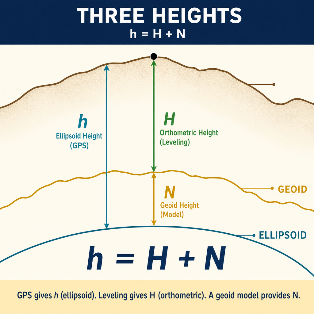
| Datum | Description |
|---|---|
| NGVD 29 | National Geodetic Vertical Datum of 1929, based on 26 tide gauges |
| NAVD 88 | North American Vertical Datum of 1988, based on one tide gauge (Rimouski, Quebec) |
| NAPGD2022 (upcoming) | Planned geoid-based datum using GNSS-derived heights |
The difference between NGVD 29 and NAVD 88 varies by location, ranging from a few centimeters to over a meter. Surveyors must identify which vertical datum applies and convert when necessary.
Map Projections
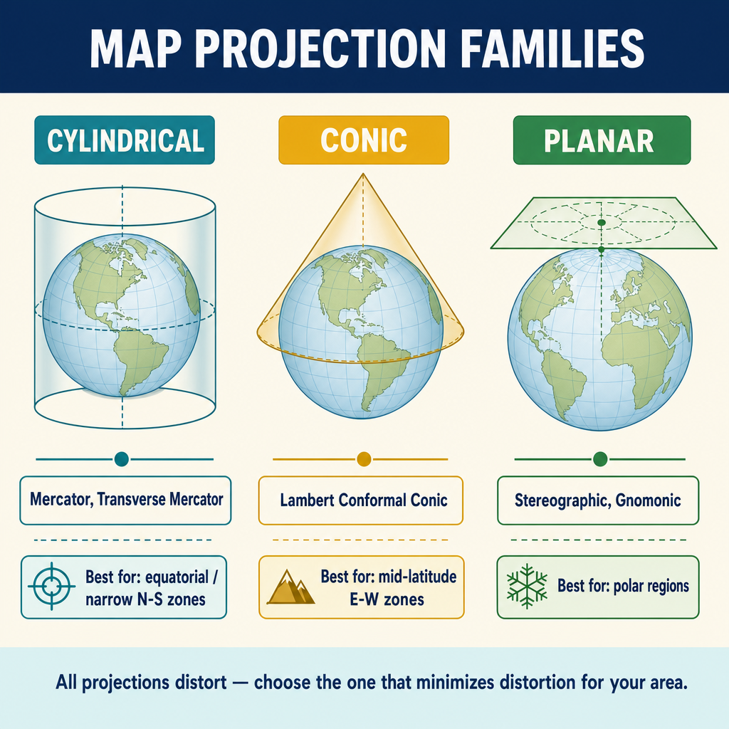
Map projections transform positions from the three-dimensional earth surface to a two-dimensional plane. Every projection introduces distortions; the choice of projection depends on which properties must be preserved.
Projection Properties
| Property | Definition | Preserved By |
|---|---|---|
| Conformal | Preserves local angles and shapes | Lambert Conformal Conic, Transverse Mercator |
| Equal area | Preserves area relationships | Albers Equal Area Conic |
| Equidistant | Preserves distances along certain lines | Equidistant Conic |
| Azimuthal | Preserves directions from a central point | Stereographic, Gnomonic |
Surveying projections are almost always conformal because preserving angles is essential for computing directions and bearings. The two conformal projections used in U.S. surveying coordinate systems are Lambert Conformal Conic and Transverse Mercator.
Lambert Conformal Conic Projection
The Lambert Conformal Conic projection projects the earth onto a cone that intersects the ellipsoid along two standard parallels (lines of latitude).
| Characteristic | Description |
|---|---|
| Projection surface | Cone intersecting at two standard parallels |
| Distortion pattern | Minimal between standard parallels, increases away from them |
| Scale factor | Less than 1.0 between standard parallels, greater than 1.0 outside them |
| Best for | Regions wider east-west than north-south |
| SPCS application | Used for zones that are wider than tall |
Scale factor behavior: On the standard parallels, the scale factor is exactly 1.0 (no distortion). Between the standard parallels, the scale factor is slightly less than 1.0. Outside the standard parallels, the scale factor is greater than 1.0.
Transverse Mercator Projection
The Transverse Mercator projection projects the earth onto a cylinder whose axis lies in the equatorial plane, tangent or secant along a central meridian.
| Characteristic | Description |
|---|---|
| Projection surface | Cylinder tangent or secant along a central meridian |
| Distortion pattern | Minimal near the central meridian, increases with distance |
| Scale factor | 1.0 on the central meridian (tangent) or on two lines parallel to it (secant) |
| Best for | Regions taller north-south than wide east-west |
| SPCS application | Used for zones that are taller than wide |
State Plane Coordinate System (SPCS)
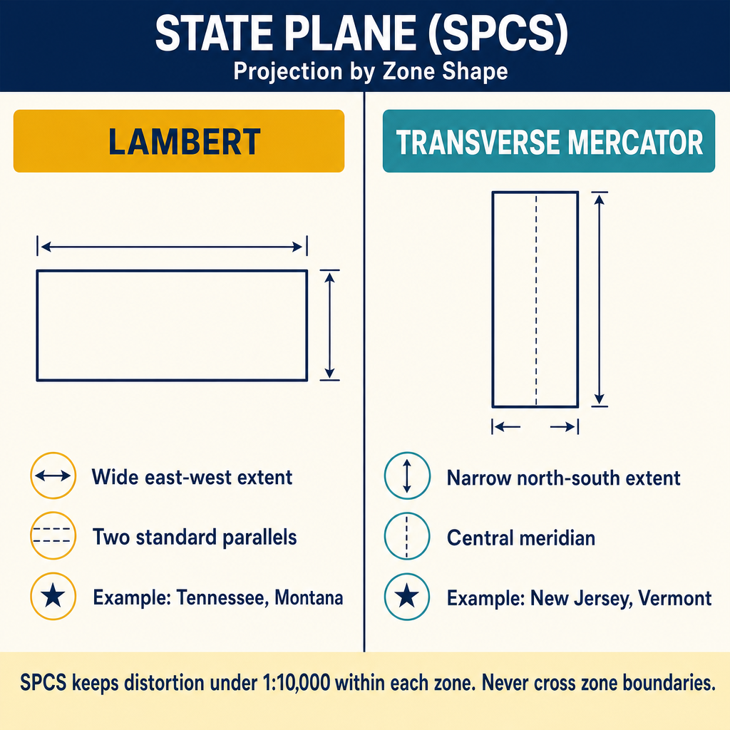
The State Plane Coordinate System divides the United States into zones, each with its own map projection chosen to minimize distortion within the zone. The maximum scale distortion in any SPCS zone is approximately 1 part in 10,000 (100 ppm).
Zone Design Principles
| Principle | Implementation |
|---|---|
| Shape determines projection | East-west zones use Lambert Conformal Conic; north-south zones use Transverse Mercator |
| Zone size limits distortion | Zones are sized to keep distortion below 1:10,000 |
| Overlap between zones | Some states have overlapping zone boundaries for border areas |
| False origin | Coordinates include false easting and false northing to avoid negative values |
SPCS83 vs. SPCS27
| Feature | SPCS 27 | SPCS 83 |
|---|---|---|
| Datum | NAD 27 | NAD 83 |
| Units | U.S. Survey Foot | Varies by state (U.S. Survey Foot or International Foot or meters) |
| Ellipsoid | Clarke 1866 | GRS 80 |
| Zone definitions | Original zones | Some zones redesigned |
Foot definitions:
- U.S. Survey Foot = 1200/3937 meters (exactly)
- International Foot = 0.3048 meters (exactly)
The difference is approximately 2 parts per million, which becomes significant over long distances. Surveyors must know which foot definition their jurisdiction uses.
Common wrong path — assuming foot definition doesn't matter for small projects. At 2 ppm, the U.S. Survey Foot vs International Foot difference is small — but it accumulates linearly with coordinate magnitude, not with project distance. A point with SPCS northing of 2,000,000 "feet" differs by 2,000,000 × 2 × 10⁻⁶ = 4 ft depending on which definition is used. That's not a rounding error; it's the difference between your monument being in the right place and 4 ft away. The effect is strongest when converting legacy coordinates: a NAD 27 coordinate labeled in "feet" without specifying whether those are Survey or International feet, converted to a modern NAD 83(2011) system, can easily land 4+ ft from the correct position if the wrong foot is assumed. States have adopted different conventions; NGS publishes the official definition for each state. Always check before converting between systems or publishing coordinates, especially on ALTA surveys and PLSS work where coordinates may pass through multiple generations of definitions.
Quick retrieval check — try before reading on.
▶A state plane northing of 1,843,275.42 is reported in "feet" without specifying which foot definition. You need to convert to meters for a deliverable. What is the difference between assuming U.S. Survey Feet vs International Feet, and how much does this matter in practical terms?
U.S. Survey Foot: 1,843,275.42 × (1200/3937) = 1,843,275.42 × 0.30480061... = 561,831.47 m.
International Foot: 1,843,275.42 × 0.3048 = 561,830.35 m.
Difference: 1.12 m (about 44 inches, or 3.7 ft).
Is this practical? For a boundary corner, absolutely — 1.12 m is catastrophic positional error, far beyond any reasonable tolerance. For topographic mapping at small scale, it may still exceed accuracy specifications. The safe practice: confirm which foot definition applies (check the state's statute or the NGS convention for the relevant SPCS zone), and either re-request the coordinates with the correct unit label or perform your own conversion using the documented foot definition. Never assume — both "foot" definitions are in active use somewhere in the US, and the 2-ppm multiplier on coordinates in the 10⁶ range makes the mismatch obvious once you check, but easy to miss if you don't.
Universal Transverse Mercator (UTM)
UTM divides the earth into 60 zones, each 6 degrees of longitude wide, using the Transverse Mercator projection.
| Parameter | Value |
|---|---|
| Number of zones | 60 (numbered 1-60 west to east from 180 degrees W) |
| Zone width | 6 degrees of longitude |
| Central meridian scale factor | 0.9996 |
| False easting | 500,000 meters |
| False northing | 0 meters (northern hemisphere), 10,000,000 meters (southern hemisphere) |
| Coverage | 84 degrees N to 80 degrees S |
UTM zone numbering: Zone 1 begins at 180 degrees W longitude. The central meridian of any zone is: CM = (zone number x 6) - 183 degrees.
Maximum distortion in UTM is approximately 1:2,500 (400 ppm), occurring at the zone boundaries. This is significantly more than SPCS and makes UTM less suitable for high-precision surveying work.
Grid-to-Ground Conversions
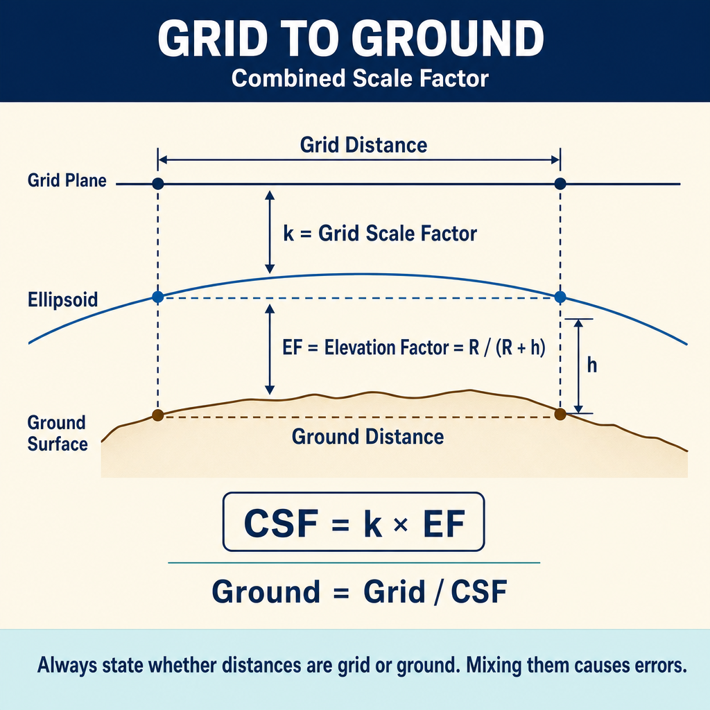
Coordinates computed on a projection grid (State Plane or UTM) differ from actual ground distances due to two factors:
Scale Factor (Grid Factor)
The scale factor accounts for the projection distortion at a given location. It converts between geodetic (ellipsoidal) distances and grid distances.
Grid distance = geodetic distance x scale factor
The scale factor varies by location within the zone. For SPCS, it ranges from approximately 0.999900 to 1.000100.
Elevation Factor
The elevation factor accounts for the difference between distances measured on the ground (at elevation) and distances on the ellipsoid surface. Points above the ellipsoid have longer ground distances than the corresponding ellipsoidal distances.
Elevation factor = R / (R + h)
where R is the mean radius of the earth and h is the elevation above the ellipsoid.
Combined Factor
The combined factor (also called the grid-to-ground factor or the project scale factor) is:
Combined factor = scale factor x elevation factor
Ground distance = grid distance / combined factor
Or equivalently:
Grid distance = ground distance x combined factor
Coordinate System Selection
| Consideration | Guidance |
|---|---|
| Project scope | Small projects may use a local coordinate system; large projects should use a standard system |
| Accuracy requirements | SPCS provides better accuracy than UTM for most survey work |
| Client requirements | Some clients or agencies require specific coordinate systems |
| Data integration | Use the same system as related datasets for easy integration |
| Zone boundaries | Avoid projects that span zone boundaries when possible |
Exam Tips
- Lambert Conformal Conic is used for SPCS zones that are wider east-west; Transverse Mercator for zones that are taller north-south
- SPCS maximum distortion is approximately 1:10,000; UTM maximum is approximately 1:2,500
- The combined factor converts between grid and ground distances and includes both scale factor and elevation factor
- NAD 27 and NAD 83 coordinates can differ by hundreds of meters -- never mix datums
- NAVD 88 and NGVD 29 differences vary by location and can exceed one meter
- U.S. Survey Foot and International Foot differ by approximately 2 ppm
- Metadata documents the quality, source, and coordinate system of spatial data
- Vector data (points, lines, polygons) is the primary GIS model for survey data
- Conformal projections preserve angles, which is why they are used for surveying
Related Test Topics
- GPS/GNSS and coordinate systems (Topic 2.4)
- Surveying computations and coordinate geometry (Topic 2.5)
- Maps, plats, and reports (Topic 2.8)
- GIS software and tools (Topic 2.12)
- Geodetic control and datums
- State Plane Coordinate System applications
Further Reading
Authoritative sources for deeper study
Snyder, USGS Bulletin 1532 — Map Projections Used by the USGS — Mathematical treatment of common map projections (Lambert Conformal Conic, Transverse Mercator, etc.).
NOAA Manual NOS NGS 5 — State Plane Coordinate System of 1983 — Definitive NGS reference for SPCS83 zone constants, projections, and conversions.
Penn State GEOG 482 — The Nature of Geographic Information — Open courseware on map projections, datums, and geospatial data fundamentals.
Wolf & Ghilani, Elementary Surveying — Chapter on map projections and the State Plane Coordinate System.
Last updated: 2026-04-17