PS Exam Preparation
Comprehensive preparation for the NCEES Principles and Practice of Surveying (PS) exam. 5 modules covering all 5 exam domains with 50 in-depth topics.
Module 1: Legal Principles
Module 2: Professional Survey Practices
Module 3: Standards & Specifications
Module 4: Business Practices
Module 5: Areas of Practice
Applicable Software & Technology
Learning Objectives
After completing this topic, you should be able to:
- Identify the major software categories used in professional surveying
- Describe CAD software capabilities for survey drafting and design
- Explain GIS software applications in survey practice
- Understand GNSS processing software and its role in survey accuracy
- Describe data collector functionality and field computing capabilities
- Identify emerging technologies affecting the surveying profession
- Evaluate software tools appropriate for specific survey applications
Overview
Software and technology are integral to modern surveying practice. From data collection through final deliverables, virtually every step of the survey process involves specialized software. The professional surveyor must understand not only how to use these tools but their capabilities, limitations, and appropriate applications.
The PS exam does not test proficiency with specific software products. Rather, it tests understanding of software categories, their functions in the survey workflow, and the surveyor's ability to evaluate whether software-produced results are reasonable. Technology changes rapidly, but the principles governing its proper use remain constant: the surveyor is responsible for the results regardless of the tools used to produce them.
Key Concepts
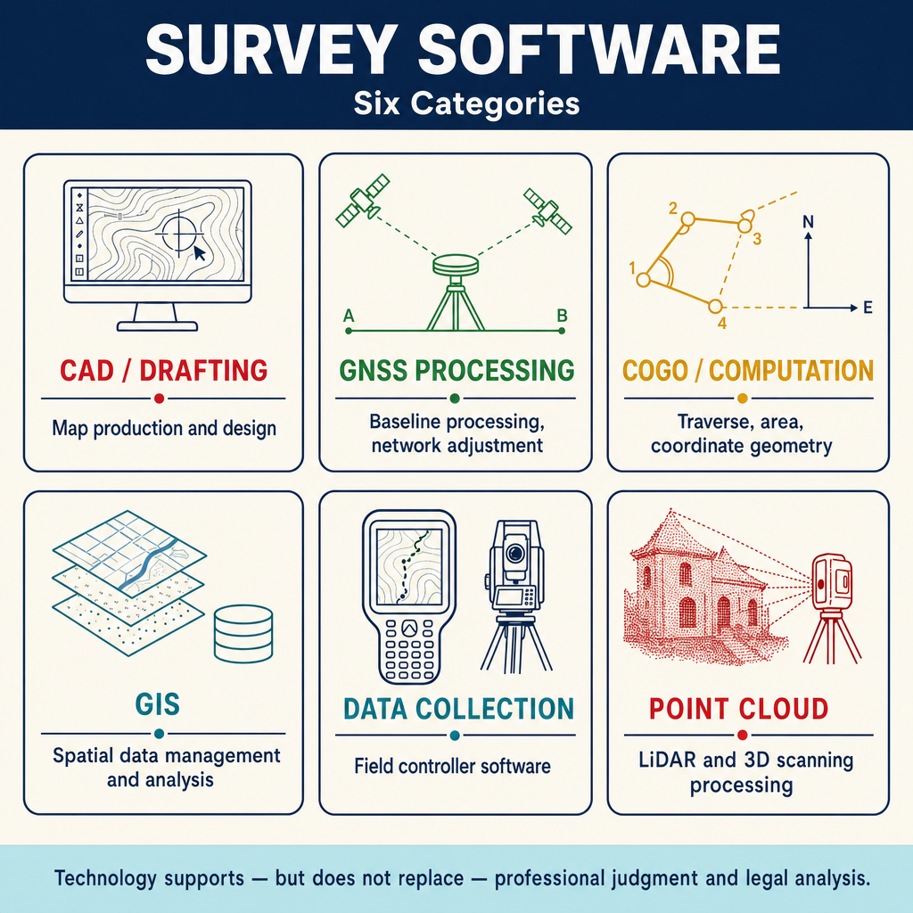
CAD Software
Computer-Aided Design (CAD) software is the primary tool for producing survey maps, plats, and construction plans. Survey-specific CAD platforms extend generic CAD with tools designed for surveying workflows.
Core CAD Capabilities for Surveying
| Capability | Application |
|---|---|
| Point management | Import, display, edit, and label survey points with codes and attributes |
| Line work generation | Create boundary lines, topographic features, and utility lines from survey data |
| Annotation | Place dimensions, labels, bearings, distances, and curve data |
| Layer management | Organize different types of information on separate layers |
| Surface modeling | Create digital terrain models (TIN, grid) from survey points |
| Sheet layout | Compose final map sheets with title blocks, legends, and scales |
| Coordinate geometry | Perform COGO computations within the CAD environment |
| Template and standards | Enforce office standards for line types, text styles, symbols, and layers |
Common Survey CAD Platforms
| Platform | Description |
|---|---|
| Autodesk Civil 3D | Full civil engineering and survey design platform |
| Bentley MicroStation/OpenRoads | Infrastructure design with survey capabilities |
| Carlson Survey | Survey-focused CAD with COGO, data collection, and surface tools |
| Trimble Business Center | Integrated survey processing and CAD |
CAD Best Practices
- Maintain consistent layer naming conventions across projects
- Use standard symbol libraries for monuments, utilities, and features
- Archive working files separately from final deliverables
- Verify mathematical accuracy of computed values (do not rely solely on graphical snapping)
- Coordinate CAD standards with the firm's data collection coding system
GIS Software
While CAD is oriented toward design and drafting, GIS excels at spatial analysis, data management, and integration of multiple data sources.
GIS Capabilities for Surveying
| Capability | Survey Application |
|---|---|
| Spatial query | Find all parcels within a specified distance of a feature |
| Overlay analysis | Identify easements, zoning, or environmental constraints affecting a property |
| Geocoding | Convert addresses or legal descriptions to geographic coordinates |
| Network analysis | Model utility networks, road systems, and drainage patterns |
| Spatial statistics | Analyze patterns in survey data, assess control network distribution |
| Data integration | Combine survey data with aerial imagery, LiDAR, assessor records, and other sources |
| Web mapping | Share survey results through interactive online maps |
| Attribute management | Store and query detailed information about survey features |
GIS Data Formats
| Format | Type | Description |
|---|---|---|
| Shapefile (.shp) | Vector | Widely used but limited (field name length, file size) |
| File geodatabase (.gdb) | Vector/Raster | Esri native format, supports complex data models |
| GeoPackage (.gpkg) | Vector/Raster | Open standard, increasingly adopted |
| GeoJSON | Vector | Web-friendly, human-readable |
| GeoTIFF | Raster | Georeferenced imagery and elevation data |
| LAS/LAZ | Point cloud | LiDAR data storage |
| KML/KMZ | Vector | Google Earth format, useful for visualization |
GNSS Processing Software
GNSS processing software converts raw satellite observations into accurate coordinates. It operates at two levels: real-time processing in the field and post-processing in the office.
Post-Processing Functions
| Function | Description |
|---|---|
| Baseline processing | Computes precise vectors between receivers using carrier phase observations |
| Ambiguity resolution | Determines the integer number of carrier wavelengths in the observation |
| Network adjustment | Adjusts multiple baselines simultaneously for consistent coordinates |
| Atmospheric modeling | Estimates or removes ionospheric and tropospheric delays |
| Antenna calibration | Applies antenna phase center offset and variation models |
| Quality assessment | Reports residuals, RMS values, and solution statistics |
| Datum transformation | Converts between reference frames and coordinate systems |
Post-Processing Workflow
The typical GNSS post-processing workflow:
- Download raw observation data from receivers
- Download base station data (CORS or local base)
- Import observation data into processing software
- Select processing parameters (elevation mask, tropospheric model, ephemeris type)
- Process baselines between receiver pairs
- Evaluate solution quality (ambiguity resolution success, RMS, residuals)
- Reprocess problem baselines with adjusted parameters if needed
- Adjust the network using least squares adjustment
- Transform coordinates to the project datum and coordinate system
- Export adjusted coordinates for use in CAD or GIS
Real-Time Processing
RTK and network RTK systems perform GNSS processing in the field:
| Feature | Description |
|---|---|
| Differential correction | Applies base station corrections to rover observations in real time |
| Ambiguity resolution | Resolves integer ambiguities on the fly |
| Position output | Provides corrected coordinates at the rover in real time |
| Quality indicators | Reports fix type (float, fixed), number of satellites, PDOP |
| Coordinate system | Can output in project coordinate system (State Plane, UTM, local) |
Data Collectors and Field Computing
Modern data collectors are specialized field computers that control survey instruments, record observations, and perform real-time computations.
Data Collector Functions
| Function | Description |
|---|---|
| Instrument control | Communicate with and control total stations, GPS receivers, and digital levels |
| Data recording | Store observations with point numbers, codes, and descriptions |
| Real-time computation | Compute coordinates, inversions, intersections, and stakeout values |
| Feature coding | Apply feature codes for field-to-finish processing |
| Stakeout | Guide the surveyor to design positions with real-time cut/fill information |
| Traverse closure | Compute preliminary closures in the field |
| Communication | Connect to base stations, networks, and office systems |
Data Collector Software Platforms
| Platform | Manufacturer | Description |
|---|---|---|
| Trimble Access | Trimble | Full-featured field software for total station and GNSS |
| Leica Captivate | Leica Geosystems | Integrated field software with touch-screen interface |
| Topcon MAGNET | Topcon | Field data collection and stakeout |
| Carlson SurvCE/SurvPC | Carlson | Third-party software supporting multiple instrument brands |
| MicroSurvey FieldGenius | MicroSurvey | Third-party data collection platform |
Computational Software
Beyond CAD and GNSS processing, surveyors use specialized computational software for:
| Application | Function |
|---|---|
| Traverse adjustment | Compute and adjust traverses using compass rule, transit rule, or least squares |
| Least squares adjustment | Rigorous network adjustment with statistical analysis |
| Coordinate transformation | Convert between coordinate systems, datums, and projections |
| Curve computation | Solve horizontal and vertical curve problems |
| Area and volume | Compute areas, volumes, and earthwork quantities |
| Legal description | Generate legal descriptions from coordinate data |
| Surface analysis | Compute contours, slopes, drainage, and sight lines from terrain models |
Remote Sensing and Scanning Technology
Terrestrial LiDAR (3D Laser Scanning)
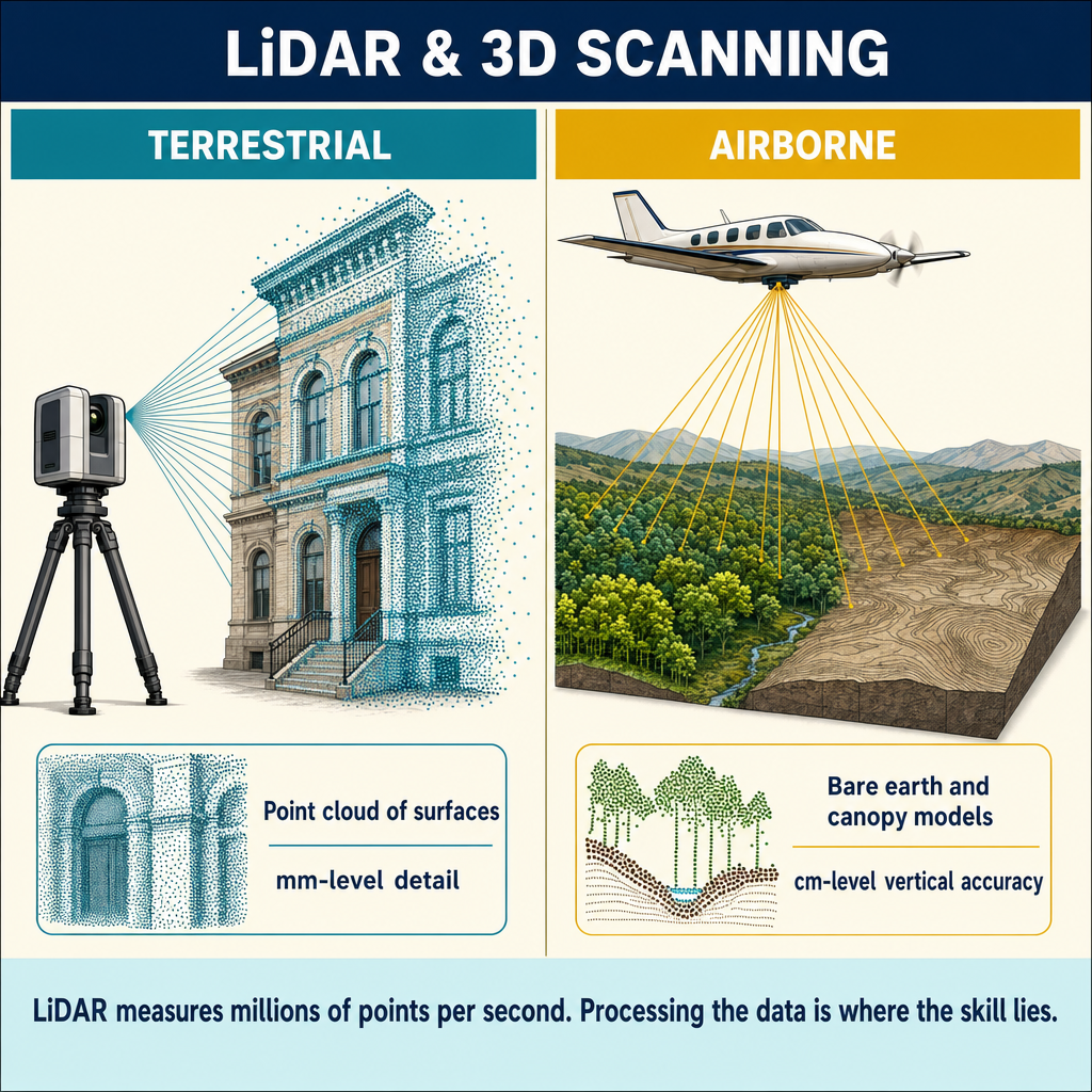
Terrestrial laser scanners collect millions of 3D points per second, creating dense point clouds of the surveyed environment:
| Application | Use in Surveying |
|---|---|
| As-built documentation | Capture existing conditions of structures and sites |
| Historic preservation | Record complex architectural features |
| Deformation monitoring | Detect movement or settlement over time |
| Industrial measurement | Document facilities, piping, and equipment |
| Accident reconstruction | Capture scene geometry for forensic analysis |
| Topographic mapping | Supplement conventional survey with dense surface data |
Unmanned Aerial Systems (UAS/Drones)
UAS technology is increasingly used in surveying for:
| Application | Description |
|---|---|
| Aerial photography | High-resolution imagery for mapping and analysis |
| Photogrammetric mapping | Generate orthoimages, elevation models, and contour maps from aerial photos |
| LiDAR scanning | Airborne LiDAR for topographic mapping of large areas |
| Construction monitoring | Track progress and compare to design |
| Volumetric computation | Calculate stockpile volumes from aerial models |
| Site inspection | Visual inspection of difficult-to-access areas |
Regulatory considerations: UAS operations in the United States require compliance with FAA regulations (Part 107 for commercial operations), including pilot certification, airspace authorization, and operational limitations.
Mobile Mapping
Vehicle-mounted scanning and imaging systems that collect data while driving:
| Technology | Application |
|---|---|
| Mobile LiDAR | Roadway mapping, corridor surveys, utility inventory |
| Street-level imagery | Visual documentation, asset inventory |
| Integrated GNSS/IMU | Provides positioning for mobile scanning platforms |
Emerging Technologies
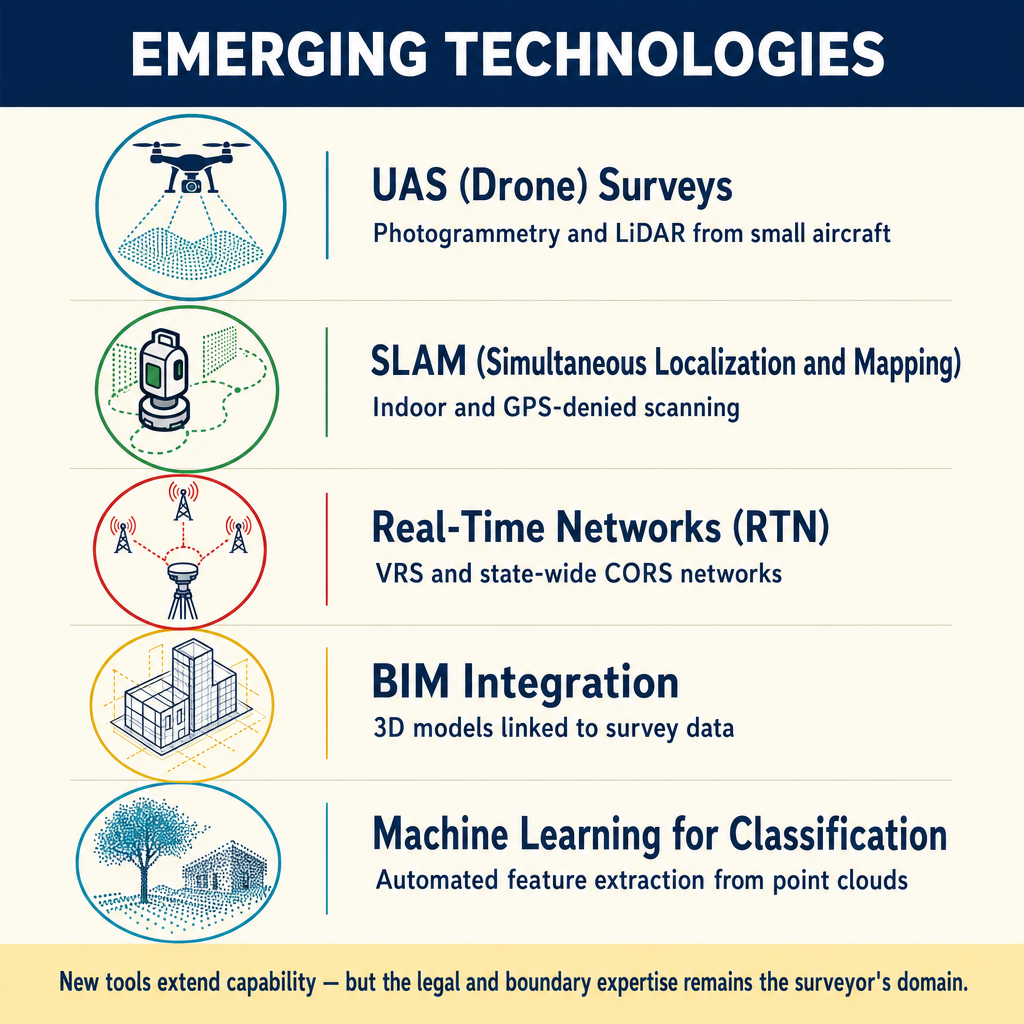
| Technology | Potential Impact on Surveying |
|---|---|
| Real-time PPP | Survey-grade positioning without base stations or networks |
| Cloud computing | Processing large datasets, collaborative workflows |
| Machine learning | Automated feature extraction from point clouds and imagery |
| Augmented reality | Visualizing design overlaid on real-world view |
| Blockchain | Immutable record-keeping for survey documents |
| Multi-frequency GNSS | Improved accuracy and faster initialization with new signals |
| Digital twins | 3D models integrating survey data with design and operational data |
Common wrong path — "the software said so, so it's right." Modern survey software is extraordinarily capable, but it is not infallible. Coordinate transformations with the wrong datum selected, traverse adjustments with missed blunders, surface models with bad breaklines, RTK fixes that are "Fixed" but wrong — all can produce output that looks professional but is fundamentally incorrect. Students sometimes rely on software output without verification; the correct professional practice is to validate software results against independent computations, known values, or at least a sanity check. A surveyor who delivers software output without review is liable for the result just as if they'd computed it by hand. Exam questions test this by describing a scenario where the software output is suspiciously clean but one key input was wrong; the correct answer is always "verify before accepting."
Quick retrieval check — try before reading on.
▶You import field data into CAD, run automated traverse adjustment, and the software reports closure of 1:75,000 — far better than required for your project. Should you accept the result and proceed to mapping, or should you verify something first?
Verify first, then proceed. A closure of 1:75,000 is suspiciously clean — so much so that it should raise a flag rather than satisfaction. Possible explanations:
-
Incorrect starting coordinates — if the starting point was coded with wrong coordinates (e.g., the wrong control point), the software computes a clean closure back to the wrong point.
-
Blunder compensation — a systematic bias (like a wrong prism constant) applied uniformly can produce tight closures that hide a real error.
-
Correct and legitimate — some traverses really are that clean, especially with modern equipment and good observing procedures.
Before accepting: (1) re-check the starting coordinates against the source control; (2) inspect the residuals for unusual patterns (all same sign, dissimilar magnitudes); (3) sanity-check by comparing one leg's bearing and distance to hand-computed expectations; (4) compare to adjacent control or published coordinates if available. Only after these checks should you accept the result. A surveyor who signs a plat based on a "1:75,000 closure" without verification is liable for whatever hidden errors the software compensated for.
Technology Management Principles
Regardless of the specific tools, professional surveyors should follow these principles:
| Principle | Application |
|---|---|
| Validation | Verify software results against independent computations or known values |
| Documentation | Record software versions, settings, and parameters used |
| Calibration | Maintain instruments and sensors per manufacturer specifications |
| Training | Ensure operators are properly trained on all tools used |
| Backup | Implement redundant data storage and disaster recovery |
| Version control | Track document revisions and maintain access to prior versions |
| Responsibility | The surveyor, not the software, is responsible for the results |
Exam Tips
- The surveyor is professionally responsible for results regardless of the software used to produce them
- GNSS post-processing requires downloading base station data and evaluating ambiguity resolution success
- Data collectors perform real-time computations in the field including traverse closure and stakeout
- CAD software is oriented toward design and drafting; GIS is oriented toward spatial analysis and data management
- UAS operations require FAA Part 107 certification for commercial use
- Least squares adjustment provides statistical quality measures that are not available from simpler adjustment methods
- Software results should always be validated against independent computations or known values
- RTK quality indicators (fix type, PDOP, number of satellites) should be monitored during data collection
- Terrestrial LiDAR collects dense point clouds but requires ground control and registration for survey accuracy
Related Test Topics
- GPS/GNSS methods and processing (Topic 2.4)
- Surveying computations (Topic 2.5)
- Data collection and quality control (Topic 2.3)
- Maps, plats, and reports (Topic 2.8)
- GIS and projections (Topic 2.9)
- Documentation and supervision (Topic 2.10)
Further Reading
Authoritative sources for deeper study
Ghilani & Wolf, Adjustment Computations (5th Ed., 2010) — Authoritative treatment of least-squares adjustment for surveying networks.
Wolf & Ghilani, Elementary Surveying — An Introduction to Geomatics (13th+ Ed.) — Comprehensive surveying text covering instruments, field procedures, and computations.
FGDC Geospatial Positioning Accuracy Standards — National standard for positional accuracy reporting (NSSDA).
Last updated: 2026-04-17