PS Exam Preparation
Comprehensive preparation for the NCEES Principles and Practice of Surveying (PS) exam. 5 modules covering all 5 exam domains with 50 in-depth topics.
Module 1: Legal Principles
Module 2: Professional Survey Practices
Module 3: Standards & Specifications
Module 4: Business Practices
Module 5: Areas of Practice
Construction Surveys
Learning Objectives
After completing this topic, you should be able to:
- Interpret construction plans including plan, profile, and cross-section views
- Calculate slope, grade, and grade elevations for construction staking
- Describe common construction staking techniques and layout methods
- Explain cut/fill calculations and earthwork volume estimation
- Understand horizontal and vertical positioning requirements for construction
- Describe as-staked records and their importance
- Identify the surveyor's role during different construction phases
Overview
Construction surveying bridges the gap between design and physical reality. The construction surveyor translates engineering plans into precise positions on the ground, enabling contractors to build structures, roads, utilities, and site improvements to design specifications. This requires the ability to read and interpret plans, perform grade and alignment calculations, stake points in the field, and maintain accurate records of what was actually built.
Construction surveying is one of the most common areas of surveying practice, and the PS exam tests both the computational aspects (slope, grade, curve layout) and the practical knowledge (staking methods, accuracy requirements, documentation).
Key Concepts
Reading Construction Plans
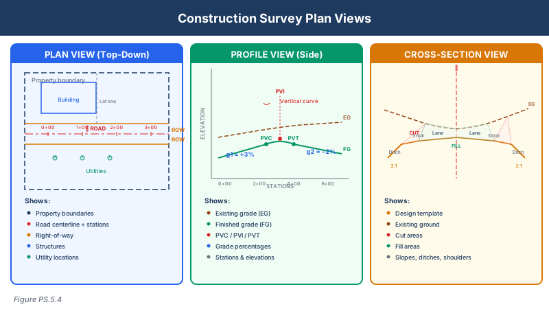
Construction plans consist of several standard views:
Plan view (top-down):
- Shows horizontal layout of the project
- Property boundaries, rights of way, easements
- Building footprints, road alignments, utility locations
- Dimensions, offsets, and station references
- North arrow, scale, and legend
Profile view (side view along alignment):
- Shows vertical design along a centerline or alignment
- Existing ground profile and proposed design profile
- Vertical curve information (PVC, PVI, PVT, curve length, grades)
- Stationing along the horizontal
- Design elevations at regular intervals and critical points
Cross-section view (perpendicular to alignment):
- Shows the design template at a specific station
- Existing ground cross-section and proposed design
- Roadway widths, slopes, ditch lines, embankment slopes
- Cut and fill areas for earthwork calculations
Detail sheets:
- Enlarged views of complex intersections, structures, or utilities
- Specific dimensions and construction details
- Material specifications and notes
Slope and Grade Calculations
Grade (gradient) is the rate of rise or fall along an alignment:
Grade (%) = (Rise / Run) x 100
Grade (ratio) = Rise : Run (e.g., 2:1 means 2 horizontal to 1 vertical)
Common calculations:
| Situation | Formula |
|---|---|
| Elevation at a point | Elev = Starting Elev + (Grade x Distance) |
| Grade between two points | Grade = (Elev2 - Elev1) / Distance |
| Distance to reach target elevation | Distance = (Target Elev - Starting Elev) / Grade |
| Slope distance from horizontal | Slope Distance = Horizontal Distance / cos(slope angle) |
Grade expression conventions:
- Positive grade = ascending in the direction of increasing station
- Negative grade = descending in the direction of increasing station
- Grades are typically expressed as percentages for roads (e.g., +3.5%)
- Cut/fill slopes are expressed as ratios (e.g., 2:1 horizontal to vertical)
Construction Staking Techniques
Route staking (roads, utilities, pipelines):
- Centerline staking -- Establish the horizontal alignment on the ground
- Slope staking -- Mark the points where cut/fill slopes intersect existing ground
- Blue tops -- Grade stakes set to finished grade elevation, painted blue on top
- Offset staking -- Stakes set at a fixed offset from the design position, with cut/fill information written on the stake
Building staking:
- Batter boards -- Horizontal boards set at a reference elevation around the building perimeter
- Building corners -- Primary layout points from which the contractor measures
- Column locations -- Individual points for structural elements
- Offset stakes -- Set away from the building to preserve reference during excavation
Utility staking:
- Invert elevations -- The elevation of the inside bottom of a pipe
- Grade boards -- Set over the trench to provide a reference for pipe grade
- Horizontal alignment -- Offset stakes showing the pipe centerline location
Stake Marking Conventions
Construction stakes communicate information to the contractor:
| Marking | Meaning |
|---|---|
| C 2.5 | Cut 2.5 feet to reach design grade |
| F 1.8 | Fill 1.8 feet to reach design grade |
| FL 425.50 | Finished elevation (flow line or finish floor) |
| STA 12+50 | Station along the alignment |
| 25' LT | Offset 25 feet left of centerline |
| TC | Top of curb |
| FL | Flow line (invert or gutter) |
| FS | Finish subgrade |
| FG | Finish grade |
Earthwork Volume Calculations
Average end area method:
Volume = [(A1 + A2) / 2] x L
Where A1 and A2 are the cross-sectional areas at consecutive stations and L is the distance between them.
Prismoidal formula (more accurate):
Volume = (L/6) x (A1 + 4Am + A2)
Where Am is the area of the cross-section at the midpoint.
Key considerations:
- Separate cut and fill volumes at transition stations where the cross-section changes from cut to fill
- Shrinkage factor: Compacted fill occupies less volume than excavated material (typically 10-30% shrinkage)
- Swell factor: Excavated material occupies more volume in the truck than in the ground (typically 10-40% swell)
- Balance point: The station where cumulative cut equals cumulative fill, minimizing haul distance
Common wrong path — mixing shrinkage and swell factors. Shrinkage and swell both describe volume changes, but they point in opposite directions and apply at different stages of earthwork:
- Swell applies when material is excavated — loosened in-situ material occupies more volume in the truck than in the ground. Typical swell: 10–40%.
- Shrinkage applies when material is placed and compacted — compacted fill occupies less volume than the source excavation. Typical shrinkage: 10–30%.
For a balanced-earthwork project, you need to decide: (a) can the excavated material fill the fill area after shrinkage? That's a shrinkage analysis on the fill side. (b) How many truck loads will move a given in-place cut volume? That's a swell analysis on the haul side. Students conflate these and compute "1.2 × cut volume = fill" or "cut volume × 0.8 = fill volume" without knowing which factor they're using. A common scenario: 10,000 CY of cut at 15% shrinkage yields 10,000 × 0.85 = 8,500 CY of compacted fill — you need to import another 1,500 CY if the fill target was 10,000 CY. Getting this backwards leads to proposing an import when you actually need an export (or vice versa). Label each factor explicitly and apply it on the correct side of the calculation.
Quick retrieval check — try before reading on.
▶A roadway project requires 25,000 CY of compacted fill. Shrinkage is 20%. Swell from excavation to the truck is 30%. How many CY of (a) in-place source material and (b) truck-load volume are required?
(a) In-place source material (cut volume): compacted fill = cut × (1 − shrinkage). So cut = 25,000 / 0.80 = 31,250 CY of in-place material must be excavated to produce 25,000 CY of compacted fill.
(b) Truck-load volume (loose): loose = in-place × (1 + swell). So loose = 31,250 × 1.30 = 40,625 CY of loose material will be in the trucks during haul.
Note that the loose volume is much larger than both the in-place and the compacted-fill volumes — this affects truck counts, haul times, and daily production rates. Applying the wrong factor (using shrinkage where swell belongs, or vice versa) can scramble the haul-cost estimate by 30–50%.
Mass Diagram
A mass diagram (mass haul diagram) plots cumulative earthwork volume against station:
- Rising curve indicates excess cut (material to be moved forward)
- Falling curve indicates excess fill (material needed from elsewhere)
- Balance points occur where the curve crosses the horizontal axis
- Maximum ordinate indicates the point of maximum accumulated cut
- Minimum ordinate indicates the point of maximum accumulated fill
- Used to plan efficient haul routes and minimize earthmoving costs
Horizontal and Vertical Positioning
Horizontal positioning requirements:
| Application | Typical Tolerance |
|---|---|
| Building layout | 1/4 inch to 1/2 inch |
| Road centerline | 0.02 to 0.05 feet |
| Bridge piers | 1/4 inch |
| Utility lines | 0.05 to 0.10 feet |
| Rough grading | 0.10 to 0.50 feet |
Vertical positioning requirements:
| Application | Typical Tolerance |
|---|---|
| Finish floor elevation | 0.01 to 0.02 feet |
| Road surface (finish grade) | 0.01 to 0.02 feet |
| Gravity sewer invert | 0.01 feet |
| Storm drainage | 0.02 to 0.05 feet |
| Rough grading | 0.05 to 0.10 feet |
As-Staked Records
After staking, the surveyor prepares as-staked records documenting:
- Actual staked positions compared to design positions
- Deviations from plan (horizontal offsets, vertical cut/fill differences)
- Date of staking and crew identification
- Conditions affecting the staking (weather, ground conditions, obstructions)
- Reference points used for the layout
As-staked records protect the surveyor by documenting exactly what was set. If construction does not match the design, these records help determine whether the problem was in the staking or in the contractor's work.
Surveyor's Role by Construction Phase
Pre-construction:
- Establish primary project control
- Verify existing conditions against design plans
- Identify potential conflicts with utilities, boundaries, or easements
During construction:
- Stake initial layout (building corners, road alignment, rough grade)
- Provide ongoing grade and alignment checks
- Stake fine grading, curbs, utilities, and finish work
- Document as-staked positions
Post-construction:
- Perform as-built surveys comparing final positions to design
- Prepare record drawings
- Certify compliance with plans and specifications (Topic 5.11)
Exam Tips
- Know the grade formula: Grade (%) = (Rise/Run) x 100; be comfortable calculating in both directions (find grade, find elevation, find distance)
- The average end area method is the most commonly tested earthwork volume formula: V = [(A1 + A2)/2] x L
- Understand cut/fill stake markings and what they communicate to the contractor
- Slope ratios in construction are expressed as horizontal:vertical (2:1 = 2 feet horizontal per 1 foot vertical)
- Gravity sewers require the tightest vertical tolerances because flow depends on precise grade
- As-staked records protect the surveyor -- they document what was actually set versus what was designed
- Blue tops indicate stakes set exactly to finish grade elevation
- Batter boards provide a reference elevation and alignment for building construction that survives excavation
- The prismoidal formula is more accurate than the average end area method but is rarely required on the exam
Related Test Topics
- Route surveys and alignment calculations (Topic 5.6)
- As-built and record drawing surveys (Topic 5.11)
- Control networks for project control (Topic 5.2)
- Topographic mapping for existing conditions (Topic 5.7)
- Surveying computations (Module 2, Topic 2.5)
- Plan reading and documentation (Module 2, Topic 2.8)
Further Reading
Authoritative sources for deeper study
Kavanagh, Surveying with Construction Applications (7th Ed.) — Chapters on construction staking, layout, and grade control.
Wolf & Ghilani, Elementary Surveying — An Introduction to Geomatics (13th+ Ed.) — Comprehensive surveying text covering instruments, field procedures, and computations.
MUTCD 2023 Part 6 — Temporary Traffic Control — Federal standard for work-zone traffic control devices and surveyor safety.
OSHA 29 CFR 1926 Subpart P — Excavations — Federal trenching and excavation safety standards relevant to construction surveyors.
Last updated: 2026-04-17