PS Exam Preparation
Comprehensive preparation for the NCEES Principles and Practice of Surveying (PS) exam. 5 modules covering all 5 exam domains with 50 in-depth topics.
Module 1: Legal Principles
Module 2: Professional Survey Practices
Module 3: Standards & Specifications
Module 4: Business Practices
Module 5: Areas of Practice
Field Surveying Techniques & Practices
Learning Objectives
After completing this topic, you should be able to:
- Describe total station operation including EDM principles and angular measurement
- Explain differential leveling procedures and sources of error
- Perform traverse design including open and closed configurations
- Identify systematic and random error sources in angular and distance measurement
- Apply proper field note procedures for various survey types
- Understand instrument calibration requirements and adjustment procedures
Overview
Field techniques form the foundation of all surveying work. Regardless of how sophisticated the office computations or how advanced the technology, the quality of a survey depends on the accuracy and reliability of the measurements collected in the field. A professional surveyor must understand not only how to use instruments but why certain procedures produce better results, how errors propagate through measurements, and how to design field procedures that meet project accuracy requirements.
This topic covers the core measurement methods used in professional surveying: total station operations, leveling, traverse, and the principles governing angular and distance measurement.
Key Concepts
Total Station Operations
A total station integrates an electronic distance meter (EDM) with a digital theodolite, allowing simultaneous measurement of horizontal angles, vertical angles, and slope distances from a single setup.
Electronic Distance Measurement (EDM)
EDM instruments measure distance using electromagnetic radiation, either infrared light or laser. The fundamental operating principles include:
| Method | Principle | Typical Application |
|---|---|---|
| Phase comparison | Measures phase shift of modulated carrier wave | Standard EDM, most total stations |
| Timed pulse | Measures round-trip travel time of laser pulse | Reflectorless measurement |
Phase comparison EDM transmits a modulated signal to a prism reflector and measures the phase difference between the transmitted and returned signals. The measured distance is calculated from the phase shift and the known modulation wavelength.
Atmospheric corrections are critical for EDM accuracy. The speed of electromagnetic radiation varies with temperature, pressure, and humidity. Most total stations accept manual entry of atmospheric conditions or apply corrections from onboard sensors.
| Atmospheric Factor | Effect on EDM | Correction Method |
|---|---|---|
| Temperature | 1 ppm per 1 degree C | Enter field temperature |
| Barometric pressure | 1 ppm per 3.5 mbar | Enter field pressure |
| Humidity | Generally negligible for infrared | May correct for long lines |
Prism constants must be set correctly. Each prism type has a characteristic offset (constant) that accounts for the difference between the optical center of the prism and the plumb point. Using an incorrect prism constant introduces a systematic error in every distance measurement.
Angular Measurement
Modern total stations use optical encoders to measure angles digitally. Key concepts include:
Direct and reverse observations -- measuring an angle in both the direct (face 1) and reverse (face 2) positions eliminates or reduces several systematic errors:
- Collimation error (line of sight not perpendicular to horizontal axis)
- Trunnion axis error (horizontal axis not perpendicular to vertical axis)
- Vertical index error
- Circle eccentricity
Repetition method -- the angle is measured multiple times with the value accumulated on the circle, then divided by the number of repetitions. This improves precision by averaging random pointing errors.
Direction method -- angles are measured as directions from a reference (initial) backsight. Multiple sets of directions are observed, with the initial circle setting advanced between sets to distribute any circle graduation errors.
Common wrong path — skipping Face 2 because "the total station corrects everything electronically." Modern total stations report "averaged" horizontal angles after a single direct-face observation, and some brochures imply that electronic compensation eliminates the need for Face 2 (reverse) observations. This is incomplete: electronic compensators handle small tilts of the vertical axis, but they do NOT correct collimation error (line-of-sight not perpendicular to horizontal axis), trunnion axis error, or vertical index error — those errors are cancelled only by taking BOTH Face 1 and Face 2 observations and averaging. Under Face 1 alone, a small residual collimation error (say 5 arc seconds) propagates into every horizontal angle with the same sign, producing a systematic bias. Exam questions bait this by asking which errors are eliminated by Face 1 + Face 2 observations; the answer is a cluster — collimation, trunnion, vertical index, circle eccentricity — NOT eliminated by Face 1 alone regardless of how modern the instrument.
Quick retrieval check — try before reading on.
▶You observe an angle using direct observation only (Face 1) with a total station that has 5" angular precision. After comparing Face 1 / Face 2 results on a control check later, you learn the instrument has a 10" collimation error. How large is the systematic bias in your Face-1-only observations, and what would Face 1 + Face 2 averaging have done?
With a 10" collimation error, every Face-1 angle is biased by approximately 10" in the same direction. Across a traverse with 6 angles, the accumulated bias is ~60" in the sum of interior angles — far more than typical allowable misclosure even for third-order work (30"√6 ≈ 73.5" allowable). So the bias can pass a closure check but the coordinates derived from those biased angles will be systematically rotated by 10" relative to where they should be. Over a 1,000-ft leg, 10" translates to about 0.048 ft of position error.
Face 1 + Face 2 averaging would have cancelled the collimation error entirely (and also trunnion-axis and vertical-index errors). The average of F1 and F2 observations is free of these instrumental biases to first order, leaving only random pointing error (the 5" precision) which is much smaller. For any work requiring second-order or better precision, F1 + F2 is non-negotiable — the electronic compensator does not substitute for it.
Differential Leveling
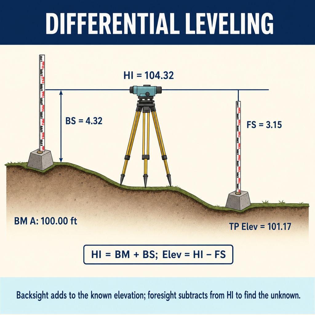
Differential leveling determines elevation differences between points using a level instrument and graduated rods. It remains the most accurate method for establishing vertical control.
Equipment and Setup
| Component | Function |
|---|---|
| Automatic level | Provides horizontal line of sight via compensator |
| Digital level | Reads bar-coded rod electronically for automated measurements |
| Level rod | Graduated staff held vertically at survey points |
| Turning plate | Stable platform for turning points during level runs |
Procedures
Three-wire leveling (or three-crosshair leveling) reads the upper stadia hair, middle crosshair, and lower stadia hair. The mean of the three readings provides the rod reading, while the stadia interval provides a distance check and helps detect blunders.
Balancing backsight and foresight distances eliminates systematic errors from:
- Earth curvature (approximately 0.0239F² feet, where F is the sight distance in thousands of feet — the effect increases with the square of distance)
- Atmospheric refraction (typically about 13% of the curvature effect, reducing the net combined effect)
- Collimation error (if the line of sight is not truly horizontal)
Reciprocal leveling is used when balanced sights are impossible (such as across a river). Observations are made from both sides, and the mean elevation difference is computed. This cancels the effects of curvature, refraction, and collimation.
Sources of Error in Leveling
| Error Source | Type | Mitigation |
|---|---|---|
| Rod not plumb | Systematic | Use rod level, careful plumbing |
| Collimation | Systematic | Balance BS/FS distances, peg test |
| Curvature and refraction | Systematic | Balance BS/FS distances |
| Settlement of turning points | Systematic | Use stable turning plates, firm surfaces |
| Temperature differential | Systematic | Avoid leveling in strong temperature gradients |
| Rod reading errors | Random/Blunder | Three-wire method, careful reading |
| Instrument settlement | Systematic | Observe BS-FS-FS-BS sequence |
The peg test (also called the two-peg test) verifies that the line of sight of the level instrument is truly horizontal. Set up midway between two points approximately 100 feet apart, read both rods, then set up near one point and read both rods. Any discrepancy reveals collimation error.
Traverse
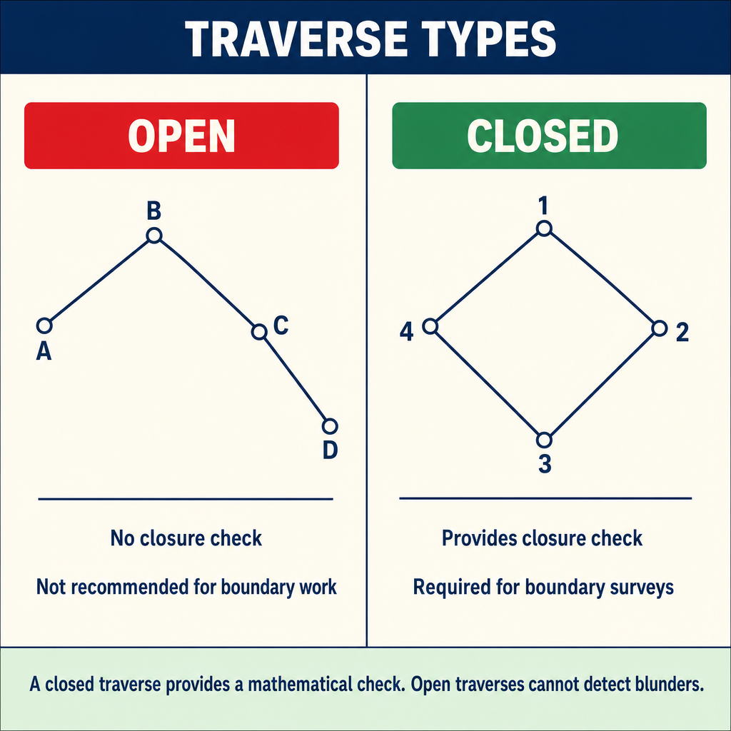
A traverse is a series of connected lines (courses) whose lengths and directions are measured. Traverses form the geometric framework for most boundary and control surveys.
Traverse Types
| Type | Configuration | Advantages | Limitations |
|---|---|---|---|
| Closed loop | Returns to starting point | Self-checking, computable closure | May not reach remote points |
| Closed connecting | Connects two known points | Self-checking, efficient for linear features | Requires two known points |
| Open | Neither closes nor connects | Can reach any area | No mathematical check on accuracy |
Open traverses should be avoided whenever possible because they provide no check on the measurements. If an open traverse is unavoidable, measurements should be repeated independently.
Angular Measurement in Traverse
At each traverse station, the interior angle (or deflection angle) is measured between the backsight and foresight directions. The angular closure of a closed traverse is computed by comparing the sum of measured angles to the theoretical sum:
- For a closed polygon with n sides: sum of interior angles = (n - 2) x 180 degrees
- The angular misclosure is the difference between the measured sum and the theoretical sum
Acceptable angular closure depends on the survey standards being applied. A common standard is the formula: allowable angular misclosure = C x square root of n, where C is a constant (such as 10 seconds, 20 seconds, or 30 seconds depending on the order of accuracy) and n is the number of angles.
Distance Measurement in Traverse
Traverse distances are typically measured with EDM. Key considerations include:
- Applying atmospheric corrections appropriate to field conditions
- Using the correct prism constant
- Measuring to properly centered and leveled targets
- Reducing slope distances to horizontal (either by the instrument or by computation)
- Applying grid or ground scale factors where coordinate systems require it
Field Notes
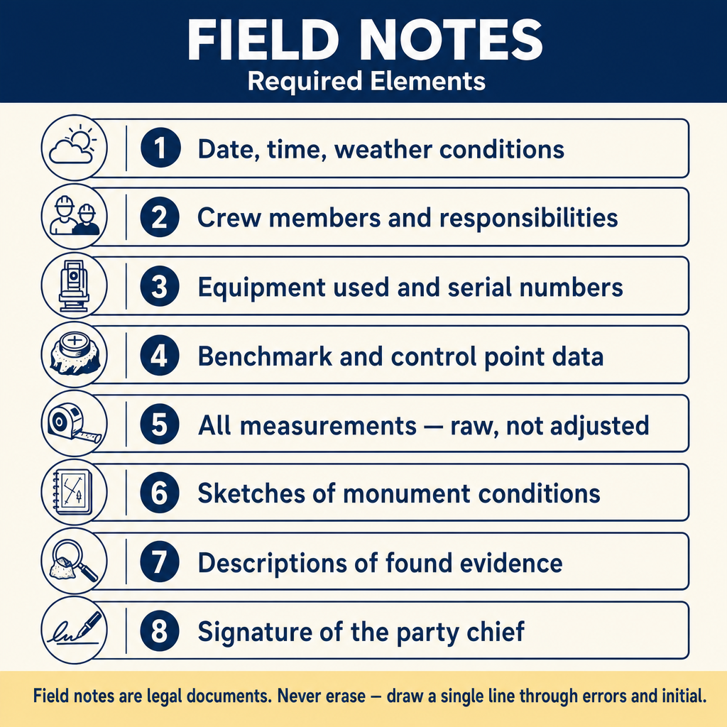
Field notes are the permanent record of observations made during a survey. They serve as the legal documentation of what was found and done in the field.
Requirements for Professional Field Notes
- Date, time, weather conditions, and crew members
- Instrument identification including make, model, and serial number
- Station descriptions and monument descriptions
- Raw observations -- all measured values as read, not adjusted or rounded
- Sketches of sufficient detail to reconstruct the survey
- Notes on evidence found -- monuments, occupation, fences, improvements
- Computation checks performed in the field
Digital Field Notes
Modern data collectors store observations electronically. However, the principles of thorough documentation remain unchanged:
- Back up data at least daily
- Maintain a written field book as a supplement to electronic records
- Record monument descriptions and evidence notes that the data collector may not capture
- Document any anomalies, instrument malfunctions, or procedural deviations
Instrument Calibration
All survey instruments require periodic calibration and verification. Key calibration procedures include:
| Instrument | Calibration Procedure | Frequency |
|---|---|---|
| Total station (angles) | Collimation check, trunnion axis check | Before each project or monthly |
| Total station (EDM) | Baseline comparison over known distances | Annually or after repair |
| Level | Peg test (two-peg test) | Before each project |
| GPS receivers | Antenna calibration verification | Per manufacturer specifications |
| Steel tape | Comparison against certified standard | Annually |
| Prisms | Constant verification | When accuracy is critical |
EDM baseline calibration involves measuring a series of known distances (typically at a calibration baseline facility) and comparing measured values to the published values. This reveals any scale error or zero offset in the EDM.
Exam Tips
- Know the errors eliminated by direct and reverse (face 1/face 2) observations -- collimation, trunnion axis, vertical index, and circle eccentricity
- Balanced backsight/foresight distances in leveling eliminate curvature, refraction, and collimation errors simultaneously
- The peg test checks for collimation error in a level instrument
- Open traverses provide no mathematical check and should be avoided
- Angular misclosure in a closed traverse is checked against (n - 2) x 180 degrees
- Atmospheric corrections for EDM depend primarily on temperature and pressure
- Prism constant errors are systematic and affect every distance equally
- Field notes are legal documents and must be complete, contemporaneous, and unaltered
Related Test Topics
- Error propagation in measurements
- Traverse adjustment methods (Topic 2.5)
- GPS/GNSS as alternative to conventional methods (Topic 2.4)
- Data collection protocols (Topic 2.3)
- Documentation requirements (Topic 2.10)
- Instrument technology (Topic 2.12)
Further Reading
Authoritative sources for deeper study
Wolf & Ghilani, Elementary Surveying — An Introduction to Geomatics (13th+ Ed.) — Comprehensive surveying text covering instruments, field procedures, and computations.
Kavanagh, Surveying with Construction Applications (7th Ed.) — Combined surveying and construction-layout reference.
Allan, Principles of Geospatial Surveying (Ethernet Edu mirror) — Survey of geospatial principles, instruments, and adjustment.
Last updated: 2026-04-17