PS Exam Preparation
Comprehensive preparation for the NCEES Principles and Practice of Surveying (PS) exam. 5 modules covering all 5 exam domains with 50 in-depth topics.
Module 1: Legal Principles
Module 2: Professional Survey Practices
Module 3: Standards & Specifications
Module 4: Business Practices
Module 5: Areas of Practice
GPS/GNSS Methods (Static, RTK, PPP)
Learning Objectives
After completing this topic, you should be able to:
- Identify the major GNSS constellations and their characteristics
- Explain the principles of satellite positioning including trilateration and signal structure
- Compare static, rapid static, RTK, PPP, and network RTK methods
- Describe CORS and VRS concepts and their application in surveying
- Identify error sources in GNSS observations and their mitigation strategies
- Select the appropriate GNSS method for a given project type and accuracy requirement
- Understand the role of carrier phase versus code-based positioning
Overview
Global Navigation Satellite Systems (GNSS) have fundamentally transformed professional surveying. Where conventional methods require line of sight between points, GNSS provides three-dimensional positioning from satellites orbiting approximately 20,200 kilometers above the earth. Understanding GNSS methods, their capabilities, their limitations, and the error sources that affect them is essential for every professional surveyor.
The term GNSS encompasses all satellite navigation systems. GPS (Global Positioning System) is the United States system, but modern survey receivers can track signals from multiple constellations simultaneously, improving accuracy, reliability, and availability.
Key Concepts
GNSS Constellations
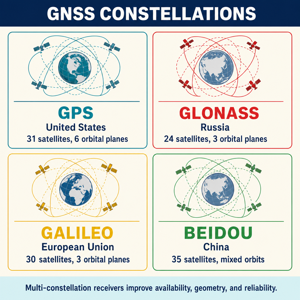
| Constellation | Country/Region | Nominal Satellites | Orbital Planes | Orbit Altitude (km) | Orbital Period |
|---|---|---|---|---|---|
| GPS (NAVSTAR) | United States | 31 (24 baseline) | 6 | 20,200 | 11 hr 58 min |
| GLONASS | Russia | 24 | 3 | 19,100 | 11 hr 15 min |
| Galileo | European Union | 30 (planned) | 3 | 23,222 | 14 hr 7 min |
| BeiDou (BDS) | China | 35 (planned) | 3 + GEO/IGSO | 21,528 (MEO) | 12 hr 53 min |
| QZSS | Japan | 4 (regional) | 3 | 32,000-36,000 | ~24 hr |
| NavIC (IRNSS) | India | 7 (regional) | -- | 36,000 (GEO/GSO) | ~24 hr |
Multi-constellation receivers track signals from two or more constellations simultaneously. Benefits include:
- More satellites available, improving geometry (lower PDOP)
- Better performance in obstructed environments (urban canyons, tree canopy)
- Faster initialization times for RTK
- Greater redundancy for quality control
Satellite Positioning Principles
Signal Structure
Each GNSS satellite transmits signals on multiple frequencies. For GPS:
| Signal | Frequency (MHz) | Wavelength (cm) | Primary Use |
|---|---|---|---|
| L1 C/A | 1575.42 | 19.0 | Navigation, code positioning |
| L1C | 1575.42 | 19.0 | Civil interoperable signal |
| L2C | 1227.60 | 24.4 | Civil code, dual-frequency |
| L5 | 1176.45 | 25.5 | Safety of life, high accuracy |
Each signal carries two types of information:
Pseudorange (code) measurement -- the receiver correlates incoming code with internally generated replica to determine satellite-to-receiver range. Accuracy: approximately 1-3 meters for standard code, better for modern signals.
Carrier phase measurement -- the receiver measures the phase of the carrier wave, providing a much more precise range measurement. The carrier wavelength (approximately 19 cm for L1) determines the fundamental measurement precision. Accuracy: a few millimeters, but requires resolving the integer ambiguity (the unknown number of full wavelengths between satellite and receiver).
Positioning Geometry
GNSS positioning requires simultaneous observations to at least four satellites:
- Three satellites determine a three-dimensional position (trilateration)
- A fourth satellite is needed to solve for receiver clock error
- Additional satellites provide redundancy and improve accuracy
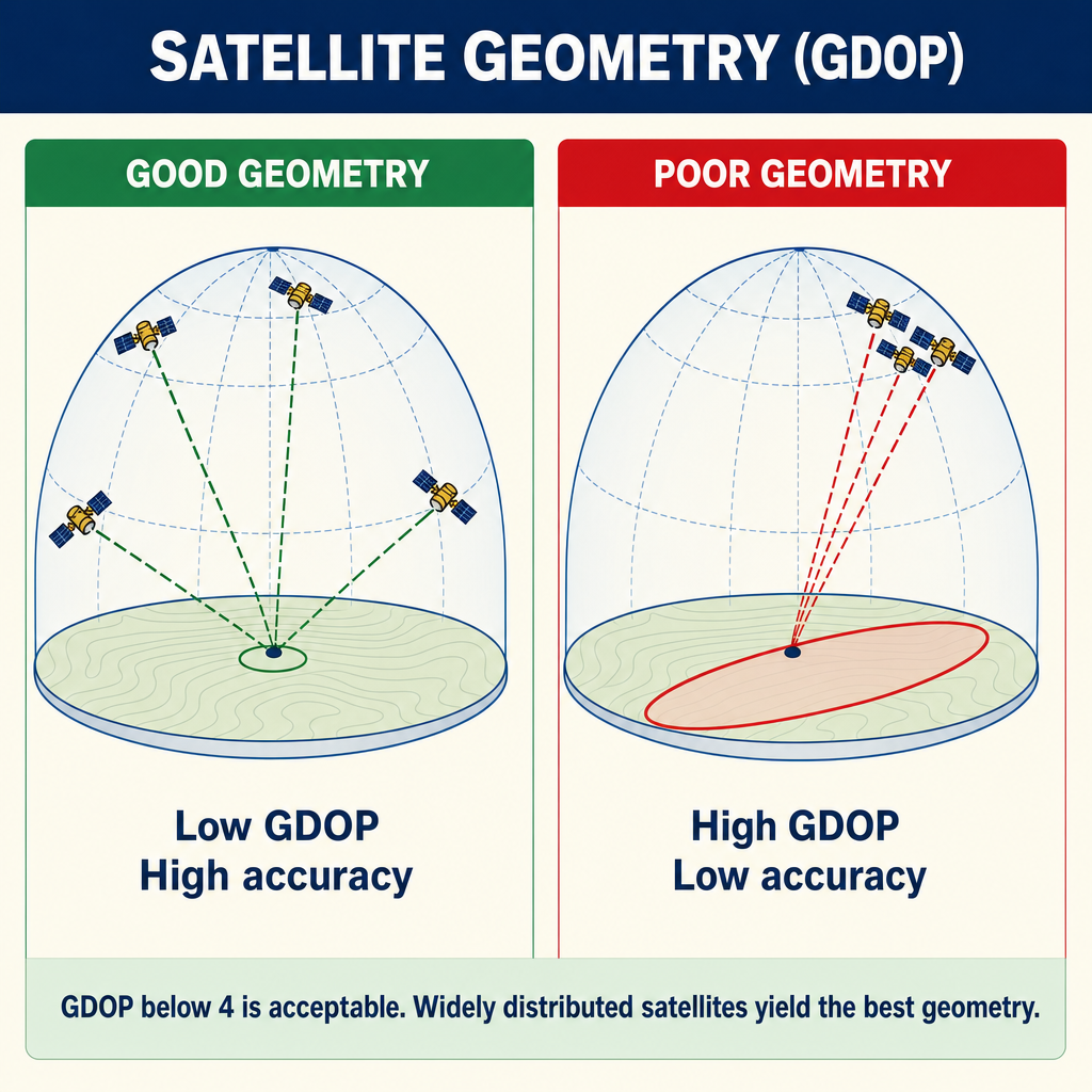
Dilution of Precision (DOP) quantifies the effect of satellite geometry on positioning accuracy:
| DOP Measure | Description |
|---|---|
| GDOP | Geometric DOP (3D position + time) |
| PDOP | Position DOP (3D position only) |
| HDOP | Horizontal DOP |
| VDOP | Vertical DOP |
| TDOP | Time DOP |
Lower DOP values indicate better geometry. A PDOP below 3 is generally considered good. PDOP above 6 indicates poor geometry, and observations should be postponed if possible.
Survey Methods
Static GPS
Application: Highest accuracy control surveys, geodetic networks, deformation monitoring.
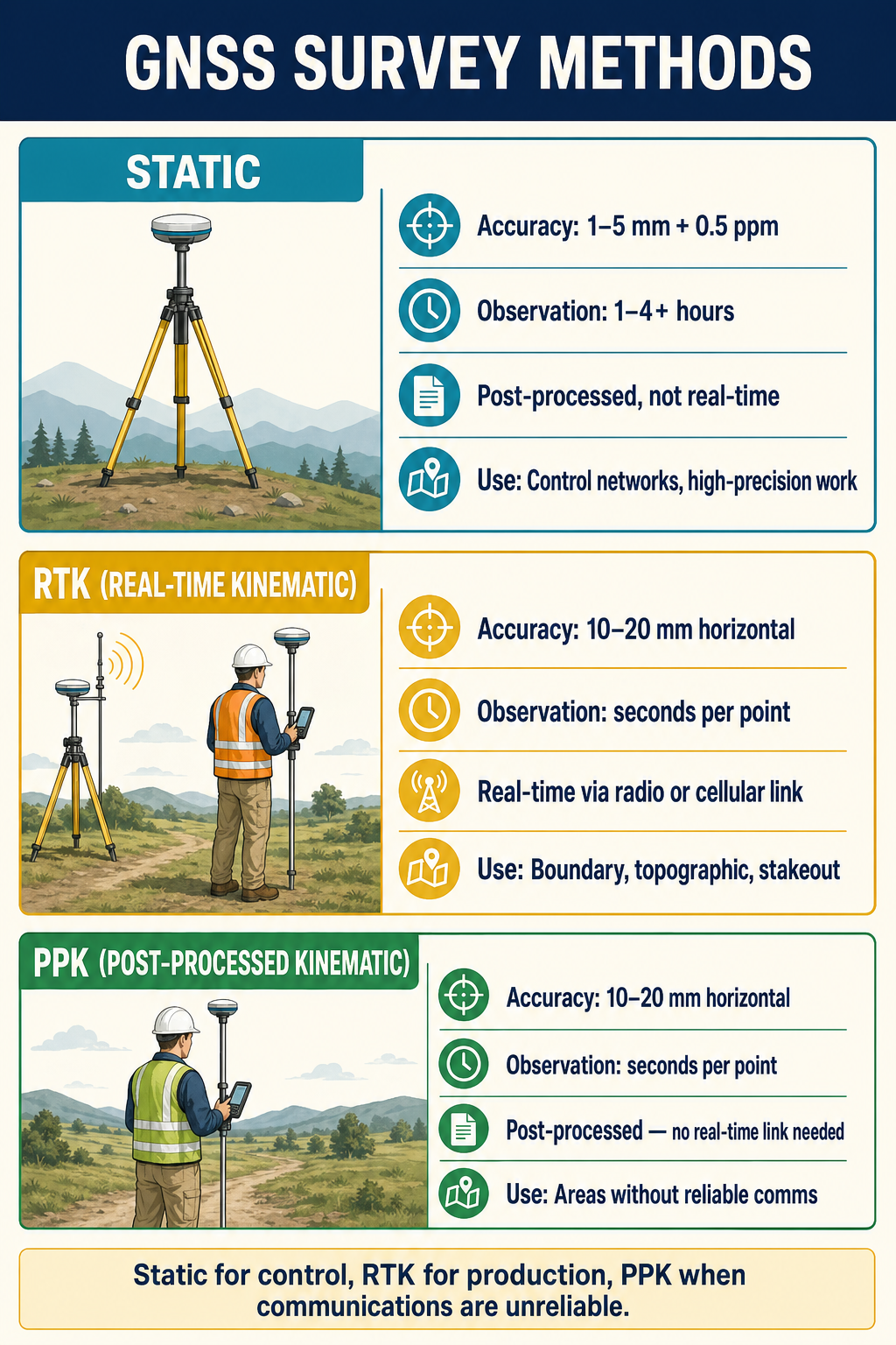
Procedure: Two or more receivers occupy known and unknown stations simultaneously for an extended period (typically 1-4 hours depending on baseline length and accuracy requirements). Data is post-processed to determine precise baseline vectors.
| Parameter | Typical Values |
|---|---|
| Occupation time | 1-4 hours (longer for long baselines) |
| Baseline accuracy | 5 mm + 0.5-1 ppm |
| Baseline length | Up to hundreds of kilometers |
| Processing | Post-processing required |
| Satellites required | 4 minimum (5+ recommended) |
| Frequency | Dual-frequency required for long baselines |
Advantages: Highest accuracy, works over long baselines, well-established methodology.
Limitations: Long occupation times, requires post-processing, inefficient for many points.
Rapid Static
Application: Control surveys where static accuracy is needed with shorter occupation times.
Procedure: Similar to static, but with occupation times of 5-20 minutes per point. Relies on advanced ambiguity resolution algorithms that can resolve integer ambiguities with shorter data spans.
| Parameter | Typical Values |
|---|---|
| Occupation time | 5-20 minutes |
| Baseline accuracy | 5-10 mm + 1 ppm |
| Baseline length | Generally under 20 km |
| Processing | Post-processing required |
Real-Time Kinematic (RTK)
Application: Boundary surveys, topographic surveys, construction staking, any work requiring centimeter-level accuracy in real time.
Procedure: A base receiver at a known point transmits corrections via radio or cellular data link to a rover receiver. The rover resolves carrier phase ambiguities and computes its position in real time, typically achieving centimeter-level accuracy.
| Parameter | Typical Values |
|---|---|
| Initialization time | Seconds to minutes |
| Position accuracy | 10-20 mm horizontal, 15-30 mm vertical |
| Baseline length | Generally under 10-15 km from base |
| Communication | UHF radio, cellular data, or internet |
| Update rate | 1-20 Hz |
Critical considerations for RTK:
- The base station must be on a known point with reliable coordinates
- Communication link reliability directly affects productivity
- Accuracy degrades with increasing baseline length
- Initialization (ambiguity resolution) must be verified by checking known points
- Multipath and signal obstructions can prevent or degrade initialization
Re-initialization check: After every initialization (or re-initialization), the surveyor should observe a known point to verify that the solution is correct. Incorrect initializations can produce positions that appear valid but are wrong by full wavelength multiples (approximately 19 cm or multiples thereof).
Common wrong path — trusting a "Fixed" solution that wasn't verified. RTK receivers report a "Fixed" status when they believe they've resolved integer ambiguities. But a Fixed status is not a guarantee of correctness — under marginal conditions (multipath near buildings, weak satellite geometry, or short initialization), a receiver can return "Fixed" on a false integer solution. The position looks precise (reported σ of 10–20 mm) but is wrong by one or more whole wavelengths — typically 19 cm on L1, sometimes meters after repeated cycle slips. The only defense is to check against a known point after each initialization, comparing the measured coordinates to the published ones. A few-cm agreement validates the fix; a 19-cm discrepancy reveals a false fix and requires re-initialization. Exam questions bait this by describing an RTK survey with "Fixed" status that produces coordinates disagreeing with control — the correct diagnosis is a false fix, not a blunder in the control or a datum issue.
Quick retrieval check — try before reading on.
▶You're running RTK near a two-story building. After initialization, the receiver reports "Fixed" with σ = 15 mm. You check a nearby CORS-tied control monument whose published coordinate is N 1,234,567.42, E 2,345,678.31. Your RTK position reads N 1,234,567.45, E 2,345,678.51. What does this tell you, and what do you do?
ΔN = +0.03 m (3 cm) — fine. ΔE = +0.20 m (20 cm) — close to one L1 wavelength (19 cm). This is a classic signature of a false fix on the east component. The receiver is confident in its solution (Fixed + 15 mm σ), but the solution is off by an integer wavelength in one axis. Do NOT accept this fix. Force a re-initialization (cover/uncover the antenna, or switch to a different base position), then re-check the known point. Repeat until the coordinates agree with published to within a few cm. Multipath from the building is the likely culprit; if re-initialization keeps producing false fixes, relocate the rover or the base station, or switch to a static session to resolve ambiguities with more observations.
Network RTK and Virtual Reference Stations (VRS)
Application: RTK positioning without establishing a local base station, using a network of permanent reference stations.
How VRS works:
- A network of continuously operating reference stations (CORS) collects GNSS observations
- A processing center models atmospheric and orbital errors across the network
- When a rover connects to the network, it sends its approximate position
- The processing center generates correction data as if a virtual reference station existed near the rover
- The rover applies these corrections to achieve RTK-level accuracy
| Parameter | Typical Values |
|---|---|
| Position accuracy | 10-20 mm horizontal, 20-40 mm vertical |
| Coverage | Within the network polygon |
| Communication | Cellular data (internet) |
| Base station required | No (uses CORS network) |
Advantages: No base station setup, consistent accuracy across the network, rapid deployment.
Limitations: Requires cellular coverage, dependent on network availability, subscription cost.
Precise Point Positioning (PPP)
Application: Positioning in remote areas without base stations or network coverage, reconnaissance surveys, GIS data collection requiring sub-decimeter accuracy.
Procedure: A single receiver collects dual-frequency observations. Post-processing uses precise satellite orbits and clocks (from organizations like the International GNSS Service) to achieve high accuracy without a base station.
| Parameter | Typical Values |
|---|---|
| Occupation time | 15 minutes to several hours |
| Position accuracy | 10-50 mm (post-processed, convergence dependent) |
| Base station required | No |
| Processing | Post-processing with precise products |
Convergence is a key concept in PPP. Unlike differential methods where ambiguities are resolved quickly, PPP solutions converge gradually as the receiver collects more data and the processing algorithm refines its estimates. Real-time PPP services are emerging but typically require 15-30 minutes for convergence.
Continuously Operating Reference Stations (CORS)
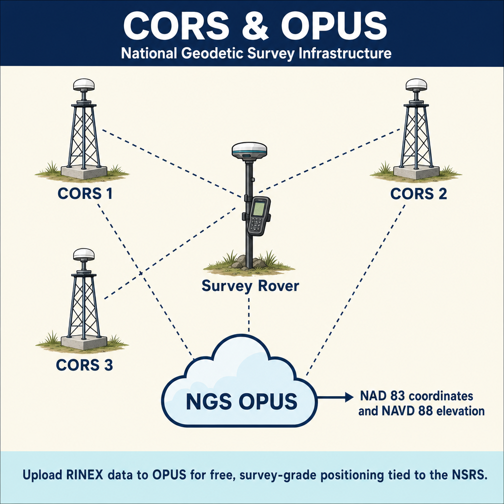
CORS are permanent GNSS receivers that operate 24/7 and provide reference data for post-processing or real-time corrections.
| CORS Network | Operator | Coverage |
|---|---|---|
| NGS CORS | National Geodetic Survey | United States |
| State CORS networks | Various state agencies | Individual states |
| Private networks | Commercial providers | Regional/national |
| IGS stations | International GNSS Service | Global |
CORS data is used for:
- Post-processing static and rapid static surveys
- Providing reference stations for network RTK
- Monitoring crustal deformation and plate tectonics
- Maintaining national spatial reference systems
GNSS Error Sources
| Error Source | Magnitude | Mitigation |
|---|---|---|
| Satellite orbit errors | 1-5 m (broadcast), cm (precise) | Use precise orbits for post-processing |
| Satellite clock errors | 1-5 m (broadcast), cm (precise) | Differential methods cancel; PPP uses precise clocks |
| Ionospheric delay | 2-50 m (varies with solar activity) | Dual-frequency observations, differential over short baselines |
| Tropospheric delay | 2-25 m (elevation dependent) | Tropospheric models, low elevation mask |
| Multipath | 0.5-5 m (code), cm (carrier) | Site selection, antenna design, long observations |
| Receiver noise | mm to cm | Averaging, carrier phase methods |
| Antenna phase center variation | mm | Calibrated antenna models, consistent antenna orientation |
| Integer ambiguity errors | Multiples of 19 cm | Verification on known points, robust algorithms |
Ionospheric Effects
The ionosphere delays GNSS code signals and advances carrier phase signals. The delay is proportional to the total electron content (TEC) along the signal path and inversely proportional to the square of the frequency.
Dual-frequency advantage: Because the ionospheric delay is frequency-dependent, receivers that track two or more frequencies can form an "ionosphere-free" linear combination that virtually eliminates ionospheric effects. This is essential for long baselines and high-accuracy work.
Tropospheric Effects
The troposphere delays GNSS signals due to the atmosphere's refractive index. Unlike ionospheric delay, tropospheric delay is not frequency-dependent and cannot be eliminated by dual-frequency combinations.
Mitigation strategies:
- Apply tropospheric models (Saastamoinen, Hopfield, or more complex models)
- Set a minimum elevation mask angle (typically 10-15 degrees) to exclude low-elevation satellites where tropospheric delay is greatest
- For high-accuracy work, estimate tropospheric delay parameters during processing
Multipath
Multipath occurs when satellite signals reach the antenna via reflected paths in addition to the direct path. Reflections from buildings, vehicles, water surfaces, and the ground cause positioning errors.
Mitigation strategies:
- Select observation sites away from reflective surfaces
- Use antennas with ground planes or choke rings
- Observe for longer periods (multipath has a characteristic period and averages out)
- Use modern signal processing techniques (narrow correlator, multipath mitigation)
Planning a GNSS Survey
Effective GNSS survey planning includes:
- Mission planning -- predict satellite availability and DOP for the project area and time period
- Site reconnaissance -- identify obstructions, multipath sources, and accessibility
- Network design -- plan baselines, session schedules, and redundancy
- Communication planning (for RTK) -- verify radio or cellular coverage
- Control -- identify existing control points for constraining the survey
- Quality checks -- plan verification procedures including checks to known points
Exam Tips
- Know the difference between code (pseudorange) and carrier phase measurements -- carrier phase is more precise but requires ambiguity resolution
- RTK initialization must always be verified by checking a known point
- Dual-frequency receivers can eliminate ionospheric delay; single-frequency cannot
- Tropospheric delay cannot be eliminated by dual-frequency combinations
- PDOP below 3 is good; above 6 is poor
- VRS/network RTK eliminates the need for a local base station but requires cellular coverage
- PPP does not require a base station but requires long convergence times
- Static GPS provides the highest accuracy but requires the longest occupation times
- Multipath is reduced by careful site selection and longer observation periods
- CORS stations provide continuous reference data for both post-processing and real-time applications
Related Test Topics
- Coordinate systems and datums (Topic 2.9)
- Surveying computations and adjustments (Topic 2.5)
- Field techniques comparison (Topic 2.2)
- Data collection quality control (Topic 2.3)
- Software for GNSS processing (Topic 2.12)
- Control survey standards and specifications
Further Reading
Authoritative sources for deeper study
Van Sickle, GPS for Land Surveyors (5th Ed.), Ch. 5 — Static, kinematic, RTK, and network methods.
Penn State GEOG 862 — GPS and GNSS for Geospatial Professionals — Free open courseware covering GNSS fundamentals, observables, RTK, and network solutions.
Leica GPS Basics (1999) — Plain-language introduction to GPS principles and field methods.
NGS Geodetic Glossary (1986, NOAA repository) — Authoritative definitions for geodetic, GNSS, and surveying terms.
Last updated: 2026-04-17