FS Exam Preparation
Comprehensive preparation for the Fundamentals of Surveying (FS) exam. 7 modules covering all 7 exam domains with 60 in-depth topics.
Module 1: Surveying Processes & Methods
Module 2: Mapping Processes & Methods
Module 3: Boundary Law & Real Property
Module 4: Surveying Principles & Geodesy
Module 5: Survey Computations
Module 6: Business Concepts
CAD & BIM Applications
Learning Objectives
After completing this topic, you should be able to:
- Describe the role of CAD in surveying and mapping
- Understand common CAD file formats and their uses
- Explain the concept of Building Information Modeling (BIM)
- Identify how surveying data integrates with CAD and BIM workflows
- Describe layer standards and drawing organization
- Understand coordinate systems in CAD environments
Overview
Computer-Aided Design (CAD) is the primary tool for creating survey maps, plats, and engineering plans. Nearly all survey deliverables -- from topographic maps to subdivision plats to construction drawings -- are produced using CAD software. Building Information Modeling (BIM) extends CAD into a 3D, data-rich environment used for design, construction, and facility management.
The FS exam tests basic understanding of CAD concepts, file formats, and how surveying data flows into digital design workflows.
Key Concepts
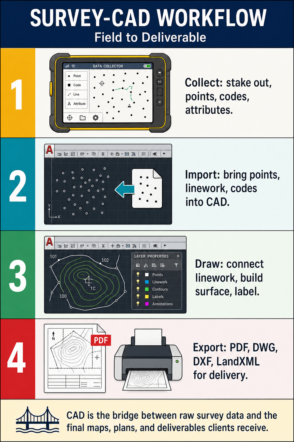
CAD in Surveying
CAD software allows surveyors to:
- Draft survey maps and plats with precise geometry, annotation, and symbology
- Import field data directly from data collectors and GNSS receivers
- Create surfaces (TINs, contour maps) from survey points
- Perform COGO computations (inverse, traverse, curve layout) within the drawing environment
- Generate legal descriptions and lot closure reports
- Produce construction drawings with plan, profile, and cross-section views
Common CAD platforms in surveying:
- Autodesk AutoCAD and Civil 3D (most widely used in the United States)
- Bentley MicroStation and OpenRoads
- Carlson Survey
- Trimble Business Center
Common File Formats
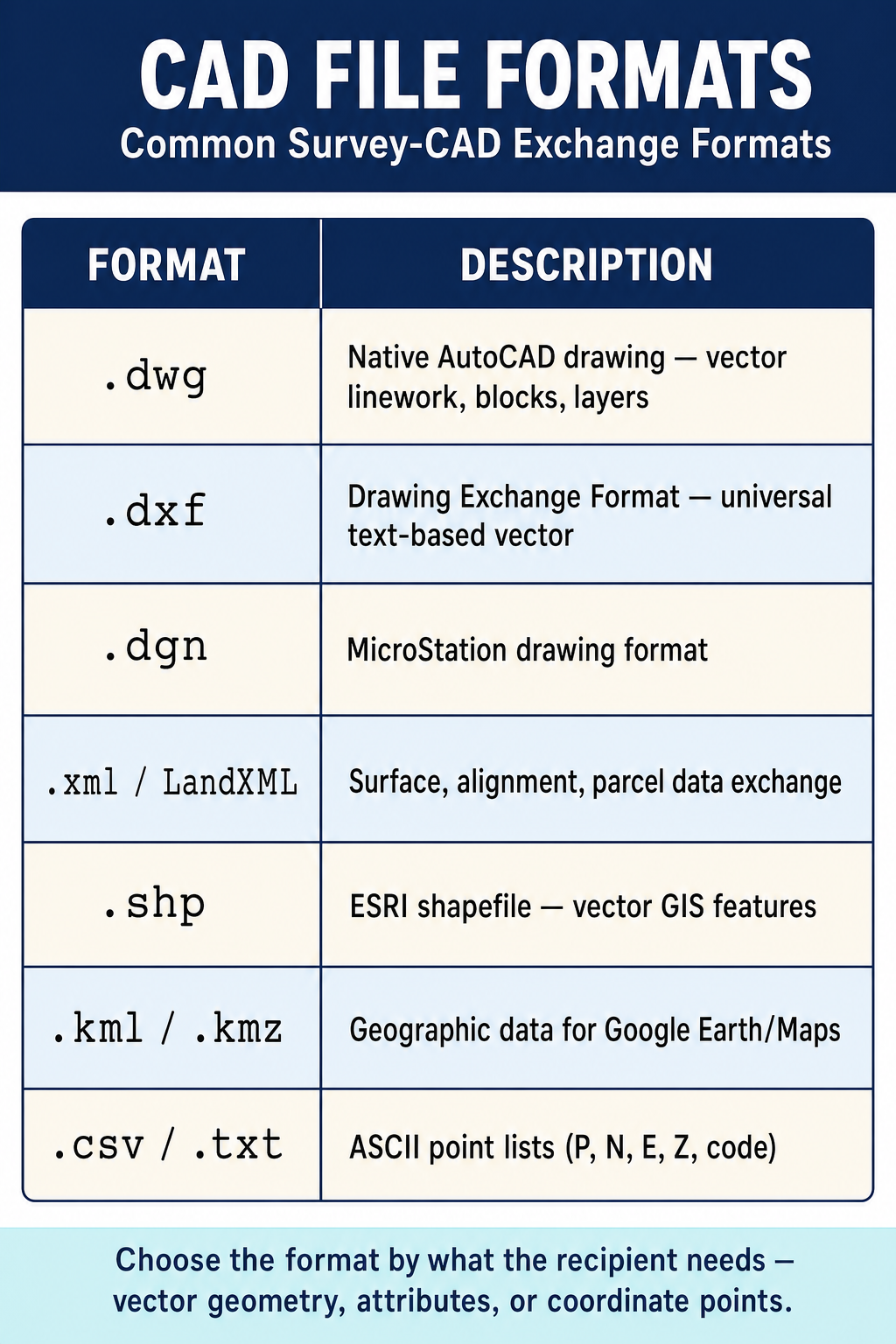
| Format | Extension | Description |
|---|---|---|
| DWG | .dwg | Native AutoCAD format; industry standard |
| DXF | .dxf | Drawing Exchange Format; for cross-platform sharing |
| DGN | .dgn | Native MicroStation format |
| Portable Document Format; for distribution | ||
| SHP | .shp | Shapefile; for GIS data exchange |
| LAS/LAZ | .las/.laz | LiDAR point cloud data |
| XML/LandXML | .xml | Structured data exchange for survey/civil data |
| CSV | .csv | Simple point data (number, northing, easting, elevation, description) |
Drawing Organization

Professional CAD drawings follow organized structures:
Layers (levels):
- Group related elements on specific layers (e.g., BOUNDARY, TOPO-CONTOUR, UTILITIES, BUILDINGS)
- Each layer has assigned properties: color, line type, line weight, visibility
- Layer standards (such as the U.S. National CAD Standard, NIBS v6 (2014)) promote consistency across projects and firms
Common layer naming conventions:
| Layer | Contents |
|---|---|
| SURVEY-BOUNDARY | Property boundary lines |
| SURVEY-MONUMENT | Monuments found and set |
| SURVEY-CONTROL | Control points and traverse |
| TOPO-CONTOUR-MAJOR | Index contour lines |
| TOPO-CONTOUR-MINOR | Intermediate contour lines |
| TOPO-FEATURE | Topographic features |
| UTIL-WATER | Water lines |
| UTIL-SEWER | Sewer lines |
| UTIL-STORM | Storm drainage |
| ROAD-CENTERLINE | Road centerlines |
| ROAD-EDGE | Edge of pavement |
Model space vs. paper space (layout):
- Model space is where geometry is drawn at full scale (1:1)
- Paper space (layout) is where the drawing is arranged for plotting at the desired scale, with title blocks, viewports, and annotation
Coordinate Systems in CAD
Survey CAD drawings should use real-world coordinates:
- State Plane Coordinates are commonly used for survey drawings in the United States
- UTM coordinates may be used for larger-scale projects
- Local coordinates (assumed datum) may be used for small projects but are generally discouraged for professional work
- The coordinate system, datum, and epoch should be clearly documented in the drawing
Scale factor considerations: State Plane and UTM coordinates include a scale factor (grid-to-ground). For construction work, coordinates may be modified to ground scale to avoid confusion with contractors.
Common wrong path — drawing at the final plotted scale instead of 1:1. CAD geometry should always be drawn at full scale (1:1) in model space, with plot scale applied only at the layout/paper space stage. Students sometimes misunderstand this and try to draw at plotted scale (e.g., drawing a 100-ft distance as 2 inches because the plot scale is 1:600). That's wrong — drawing at plot scale destroys the mathematical usability of the CAD file, makes coordinate queries produce wrong values, and breaks integration with design software. Always draw at 1:1 (a 100-ft distance drawn as 100 units in CAD); set plot scale in the viewport when laying out the sheet for plotting. Exam questions test this by asking what scale geometry should be at in model space — the answer is always 1:1, regardless of what the final plot scale will be.
Quick retrieval check — try before reading on.
▶A surveyor needs to plot a drawing at 1:600 scale (1 inch = 50 ft) on 24" x 36" paper. In model space, what length should a 250-ft boundary line be drawn as, and why?
250 units — in other words, full scale (1:1). If the CAD file's base unit is feet, the line is 250 feet. If the file uses inches, it is 3,000 inches. Either way, it represents the actual 250 feet of ground distance, not the 5 inches (250/50) it will appear on the plotted paper.
Why 1:1? Because CAD geometry must correspond to real-world coordinates. If you drew the line as 5 units (scaled to 1:600), then:
- Coordinate queries would return 5 units where a 250-ft line should be — obviously wrong
- Inserting the file into another design would have 120× scale error
- Coordinate-based calculations (closure, area) would produce meaningless results
- Integration with GIS, BIM, or other CAD files would fail
Plot scale is applied at the layout/paper space stage: create a viewport in paper space sized to show the desired area at the plot scale, and CAD automatically applies the scale factor during plotting. Model space remains at 1:1 always. This separation of concerns is the foundation of modern CAD practice.
Building Information Modeling (BIM)
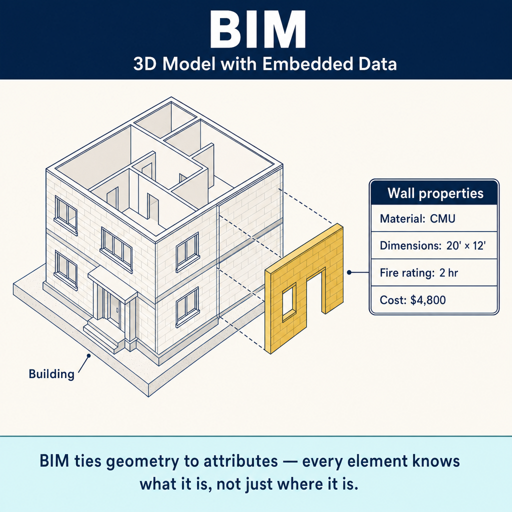
BIM is a 3D model-based process that provides design, construction, and facility management professionals with tools to plan, design, construct, and manage buildings and infrastructure.
How surveying supports BIM:
- Existing conditions survey provides the base data for the BIM model
- As-built surveys verify that construction matches the BIM model
- Point clouds from laser scanning (terrestrial or mobile) create detailed 3D representations of existing structures
- Control surveys provide the coordinate framework for the BIM model
Key BIM concepts:
- BIM objects contain both geometry (shape, position) and data (material, cost, specifications)
- BIM enables clash detection (identifying conflicts between building systems before construction)
- The level of detail in a BIM model is described by LOD (Level of Development), defined by the BIMForum LOD Specification and referenced in AIA Document E203 (BIM and Digital Data Exhibit)
- Common BIM platforms include Autodesk Revit, Bentley OpenBuildings, and Trimble Tekla
Data Exchange Between Survey and Design
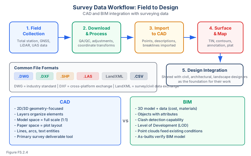
The flow of data from field to design follows a typical path:
- Field collection: Data collector or GNSS rover records points, lines, and attributes
- Download and process: Raw data is downloaded, checked for quality, and processed
- Import to CAD: Processed data (coordinates, descriptions) is imported into the CAD environment
- Surface creation: Points and breaklines generate a TIN or DTM
- Map production: Contours, features, and annotation are drafted to create the survey deliverable
- Design integration: The survey base map is shared with designers (civil, architectural, landscape) as the foundation for their work
Exam Tips
- DWG is the industry-standard CAD format; DXF is the exchange format for cross-platform sharing
- CAD drawings should use real-world coordinates tied to a defined coordinate system (State Plane, UTM, etc.)
- Geometry is drawn at full scale (1:1) in model space; scaling happens in paper space/layout
- Layer organization is critical for professional drawings; follow established naming conventions
- BIM extends CAD with data-rich 3D models that include geometry and attributes
- LandXML is a common format for exchanging survey and civil engineering data between platforms
- The FS exam may test basic understanding of file formats, coordinate systems in CAD, or data flow from field to design
- Understanding model space vs. paper space is important for interpreting scale and annotation
Related Test Topics
- Digital Terrain Models (Topic 2.6)
- GIS and Spatial Analysis (Topic 2.5)
- State Plane Coordinates (Module 4, Topic 4.6)
- Plan and Profile Drawings (Topic 2.2)
Further Reading
Authoritative sources for deeper study
Kavanagh, Surveying with Construction Applications (7th Ed.) — Combined surveying and construction-layout reference.
Wolf & Ghilani, Elementary Surveying — An Introduction to Geomatics (13th Ed., 2012) — Comprehensive surveying text covering instruments, field procedures, and computations.
FGDC Geospatial Positioning Accuracy Standards — National standard for positional accuracy reporting (NSSDA).
Last updated: 2026-04-17