FS Exam Preparation
Comprehensive preparation for the Fundamentals of Surveying (FS) exam. 7 modules covering all 7 exam domains with 60 in-depth topics.
Module 1: Surveying Processes & Methods
Module 2: Mapping Processes & Methods
Module 3: Boundary Law & Real Property
Module 4: Surveying Principles & Geodesy
Module 5: Survey Computations
Module 6: Business Concepts
Construction Surveys & Staking
Learning Objectives
After completing this topic, you should be able to:
- Describe the types of construction staking and their purposes
- Calculate cut and fill values from design and existing grades
- Explain slope staking procedures and calculations
- Understand offset staking and why it is used
- Read and interpret grade sheets and staking notes
- Describe as-built survey requirements
Overview
Construction surveying translates engineering designs from paper (or digital models) to the physical ground. The surveyor stakes the horizontal and vertical positions of proposed improvements -- buildings, roads, utilities, grading -- so that contractors can build the project to the design specifications.
Construction staking requires precision, clear communication with contractors, and a thorough understanding of engineering plans. It is one of the most common tasks for entry-level surveyors, making it a frequent topic on the FS exam.
Key Concepts
Types of Construction Staking
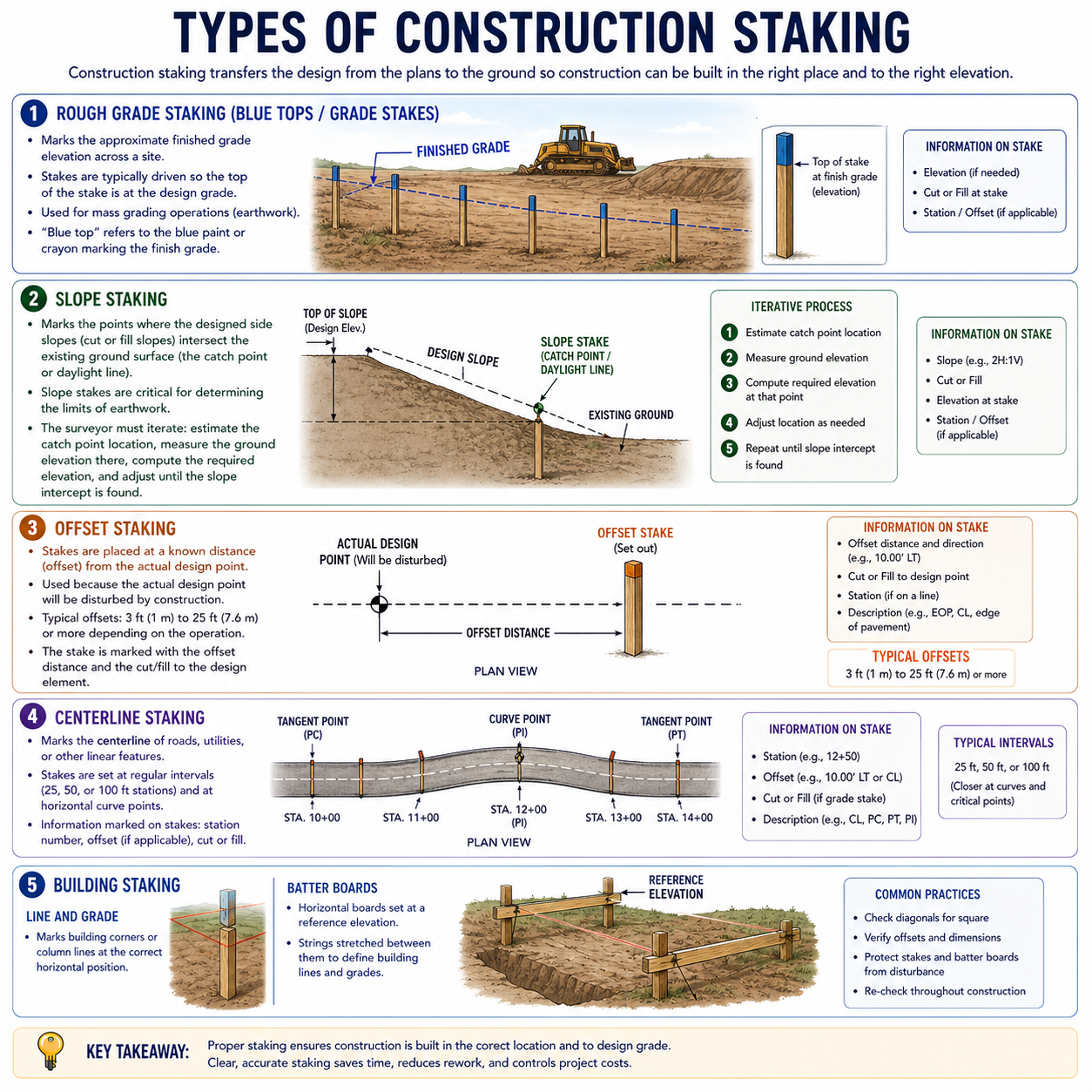
Rough grade staking (blue tops / grade stakes):
- Marks the approximate finished grade elevation across a site
- Stakes are typically driven so the top of the stake is at the design grade
- Used for mass grading operations (earthwork)
- "Blue top" refers to the blue paint or crayon marking the finish grade
Slope staking:
- Mark the points where the designed side slopes (cut or fill slopes) intersect the existing ground surface (the catch point or daylight line)
- Slope stakes are critical for determining the limits of earthwork
- The surveyor must iterate: estimate the catch point location, measure the ground elevation there, compute the required elevation, and adjust until the slope intercept is found
Offset staking:
- Stakes are placed at a known distance (offset) from the actual design point
- Used because the actual design point will be disturbed by construction
- Typical offsets: 3 ft (1 m) to 25 ft (7.6 m) or more depending on the operation
- The stake is marked with the offset distance and the cut/fill to the design element
Centerline staking:
- Marks the centerline of roads, utilities, or other linear features
- Stakes are set at regular intervals (25, 50, or 100 ft stations) and at horizontal curve points
- Information marked on stakes: station number, offset (if applicable), cut or fill
Building staking:
- Line and grade: Marks building corners or column lines at the correct horizontal position
- Batter boards: Horizontal boards set at a reference elevation, with strings stretched between them to define building lines and grades
Cut and Fill Calculations
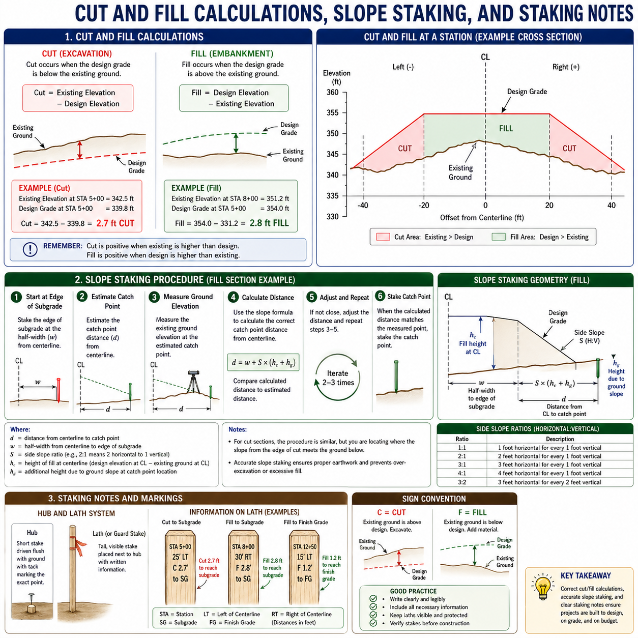
Cut occurs when the design grade is below the existing ground:
Fill occurs when the design grade is above the existing ground:
Example: The existing ground elevation at station 5+00 is 342.5 ft. The design grade is 339.8 ft.
- Cut = 342.5 - 339.8 = 2.7 ft cut
Example: The existing ground elevation at station 8+00 is 351.2 ft. The design grade is 354.0 ft.
- Fill = 354.0 - 351.2 = 2.8 ft fill
Slope Staking Procedure
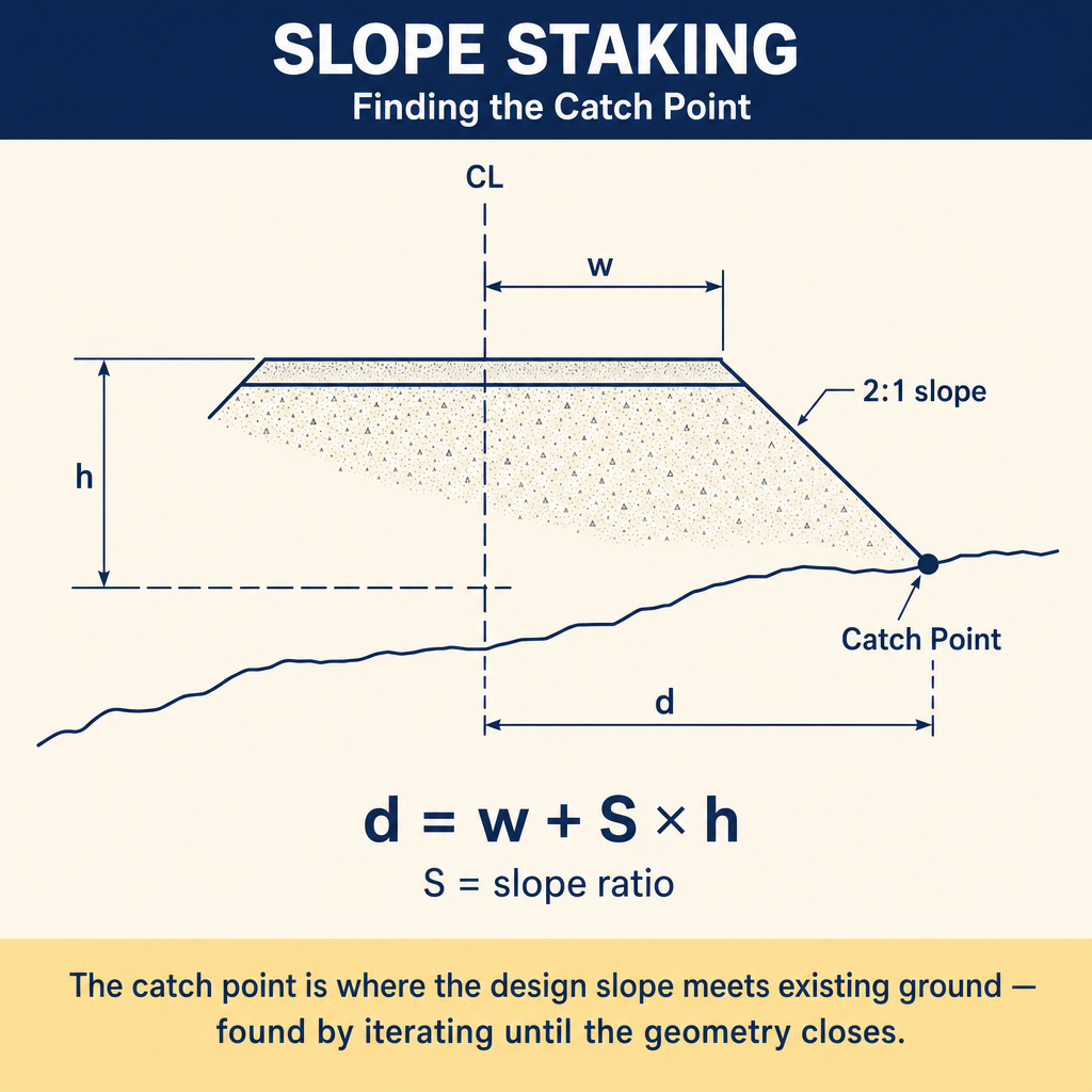
Slope staking finds the catch point where the designed side slope meets the existing ground.
Given information:
- Design centerline elevation and cross-section width (half-width from centerline to edge of subgrade)
- Side slope ratio (e.g., 2:1 means 2 horizontal to 1 vertical)
- Existing ground cross-section
Procedure for a fill section:
- Start at the edge of the subgrade (half-width from centerline)
- Estimate the catch point distance from centerline
- Measure the ground elevation at the estimated catch point
- Calculate: Distance from edge = fill height at edge multiplied by slope ratio
- If the calculated distance does not match the estimated distance, adjust and repeat
- Iterate until the catch point is found (usually 2-3 iterations)
Catch point distance formula (fill):
Where d is the distance from centerline to catch point, w is the half-width of the subgrade, S is the slope ratio, h_c is the height of fill at centerline, and h_g is the additional height due to ground slope.
Staking Notes and Markings
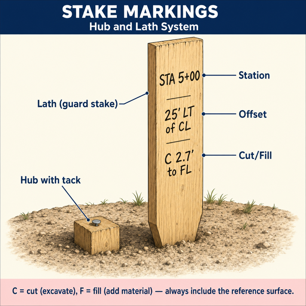
Construction stakes are marked with specific information that the contractor needs:
Hub and lath system:
- A hub is a short stake driven flush with the ground, with a tack marking the precise point
- A lath (or guard stake) is a tall, visible stake placed next to the hub, with written information
Information on the lath:
- Station number (e.g., STA 5+00)
- Offset distance and direction (e.g., 25' LT of CL)
- Cut or fill to the design element (e.g., C 2.7' to FL = cut 2.7 feet to flow line)
- The reference (what the cut/fill is to): subgrade, flow line, finish grade, top of curb, etc.
Sign convention:
- C = Cut (existing ground is above design; excavate)
- F = Fill (existing ground is below design; add material)
- V (chevron mark) = Finished grade is at the marked line on the stake -- no cut or fill; a construction reference point is directly at the stake mark
Where the cut/fill is measured from. Three conventions are in common use; a surveyor must know which one a given contractor expects:
- From a marked line on the stake. The surveyor draws a horizontal line on the stake and writes "C 3.0" or "F 2.5" meaning the finished grade is that distance below (cut) or above (fill) the line. Advantage: the cut/fill value can always be a whole number by choosing where to mark the line -- easier for the contractor to read.
- From the ground at the stake. "C 2.7" or "F 1.5" measured from existing ground, not from a line on the stake. Simpler to compute but the cut/fill value is usually an odd number (2.7, 1.5, 8.3).
- From the top of the stake. Used when the top of the stake itself is set to a specific elevation. These are called red tops (top of stake = subgrade elevation) or blue tops (top of stake = base-course elevation), with the stake tops painted for visibility.
Cut-to-even-footmark technique. When the ground-to-design difference is uneven (e.g., 7.4 ft cut), the surveyor can mark the stake at an even foot above ground (0.6 ft above ground in this example, giving a 8.0 ft total cut from that mark) and write "C 8.0" on the stake. The contractor now has a whole-number cut from a visible horizontal reference. The math: if the computed cut from the ground is 7.4 ft and you want to mark the stake for an even 8.0 ft cut, draw the line 8.0 − 7.4 = 0.6 ft above the ground. The contractor reads "C 8.0" as cut 8.0 ft below the marked reference line (not 8.0 ft below the ground), which produces the same final design grade as cutting 7.4 ft below the ground. Source: Basic Surveying Manual (Wisconsin LTAP, 2002), "Calculating cut and fill."
Common wrong path — cut/fill sign confusion under stake markings. On a stake, "C 2.7" means the existing ground must be cut 2.7 ft to reach design — that is, the design grade is 2.7 ft below the existing ground. Students reading stakes sometimes confuse this with "the design elevation is 2.7 ft" or "C means climb 2.7 ft up from here." Neither is correct. The stake marking tells the contractor what action is required: cut (excavate) or fill (add material). A stake marked "F 1.8" means fill 1.8 ft — the design grade is 1.8 ft above the existing ground. When computing cut/fill from an elevation difference, remember: cut = existing − design (positive when excavating); fill = design − existing (positive when filling). The stake shows the magnitude and operation, not the final design elevation directly. Exam questions test this by giving existing and design elevations and asking what to mark on the stake.
Quick retrieval check — try before reading on.
▶At station 12+50, the existing ground elevation is 428.6 ft and the design grade is 425.2 ft. What should the stake be marked as? What if the situation were reversed (existing 425.2, design 428.6)?
First case: Existing (428.6) is higher than design (425.2). Cut = 428.6 − 425.2 = 3.4 ft. Mark the stake: "C 3.4" (cut 3.4 feet to reach design grade).
Reversed case: Existing (425.2) is lower than design (428.6). Fill = 428.6 − 425.2 = 3.4 ft. Mark the stake: "F 3.4" (fill 3.4 feet to reach design grade).
The magnitude is the same (3.4 ft), but the operation is opposite. The contractor needs to know whether to excavate or add material; just telling them "3.4" without the C or F is ambiguous and dangerous. Always include the C/F indicator on the stake, along with the reference surface (subgrade, finish grade, flow line, etc.) so there's no ambiguity about what design element the cut/fill references.
As-Built Surveys
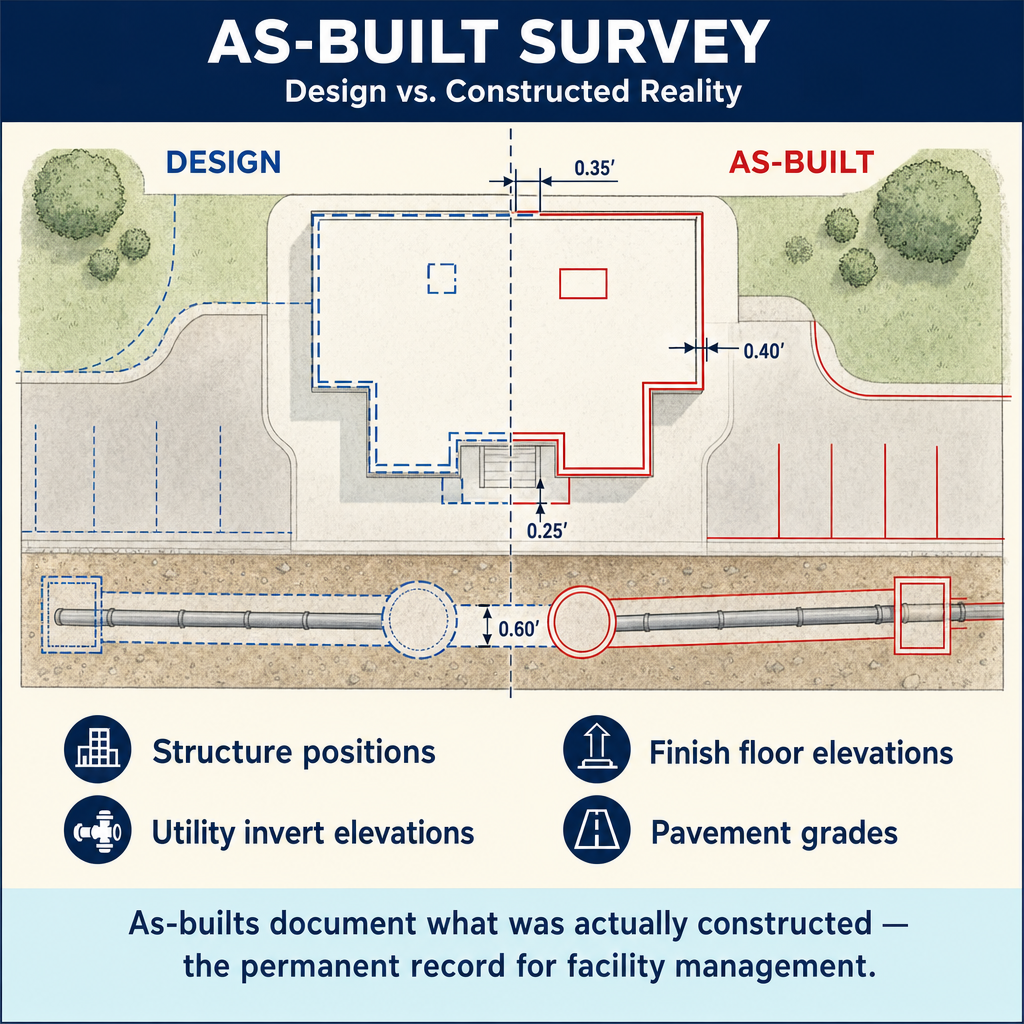
After construction is complete, an as-built survey documents the actual locations and elevations of constructed improvements.
Purpose:
- Verify that construction matches the design within specified tolerances
- Create permanent records for facility management
- Document utility locations for future reference
- Satisfy regulatory and permit requirements
Common as-built requirements:
- Horizontal and vertical position of structures
- Invert elevations and alignment of underground utilities
- Finish floor elevations
- Pavement grades and cross-slopes
- Storm water facilities (detention, retention, drainage structures)
Exam Tips
- Cut = existing is higher than design (excavate); Fill = existing is lower than design (add material)
- Offset staking is used because the actual design point will be disturbed by construction equipment
- Slope staking finds the catch point (daylight line) where the side slope meets existing ground
- A 2:1 slope means 2 feet horizontal for every 1 foot vertical; a 3:1 slope is flatter than a 2:1 slope
- Know how to read stake markings: station, offset, cut/fill, reference surface
- Blue tops are grade stakes driven to the design elevation
- Batter boards are used for building layout; strings between batter boards define building lines
- The FS exam commonly tests cut/fill calculations given existing and design elevations
- As-built surveys document what was actually built versus what was designed
Related Test Topics
- Levels and Instruments (Topic 1.2)
- Topographic Surveys (Topic 1.7)
- Route Surveying and Alignments (Module 4, Topic 4.3)
- Land Development and Subdivisions (Topic 1.9)
Further Reading
Authoritative sources for deeper study
Kavanagh, Surveying with Construction Applications (7th Ed.) — Chapters on construction staking, layout, and grade control.
Wolf & Ghilani, Elementary Surveying — An Introduction to Geomatics (13th Ed., 2012) — Comprehensive surveying text covering instruments, field procedures, and computations.
MUTCD 2023 Part 6 — Temporary Traffic Control — Federal standard for work-zone traffic control devices and surveyor safety.
OSHA 29 CFR 1926 Subpart P — Excavations — Federal trenching and excavation safety standards relevant to construction surveyors.
Last updated: 2026-04-17