FS Exam Preparation
Comprehensive preparation for the Fundamentals of Surveying (FS) exam. 7 modules covering all 7 exam domains with 60 in-depth topics.
Module 1: Surveying Processes & Methods
Module 2: Mapping Processes & Methods
Module 3: Boundary Law & Real Property
Module 4: Surveying Principles & Geodesy
Module 5: Survey Computations
Module 6: Business Concepts
Photogrammetry Principles
Learning Objectives
After completing this topic, you should be able to:
- Define photogrammetry and its applications in surveying
- Calculate photo scale from focal length and flying height
- Explain relief displacement and its effect on aerial photographs
- Describe the concept of stereoscopic viewing and parallax
- Understand ground control requirements for photogrammetric mapping
- Distinguish between orthophotos and perspective photographs
Overview
Photogrammetry is the science of making measurements from photographs. In surveying, photogrammetry typically involves aerial photographs (taken from aircraft or drones) used to create topographic maps, orthophotos, and digital terrain models. By analyzing overlapping photographs, photogrammetrists can extract precise three-dimensional positions of features on the ground.
The FS exam tests fundamental photogrammetric concepts including photo scale, relief displacement, stereoscopic principles, and ground control requirements.
Key Concepts
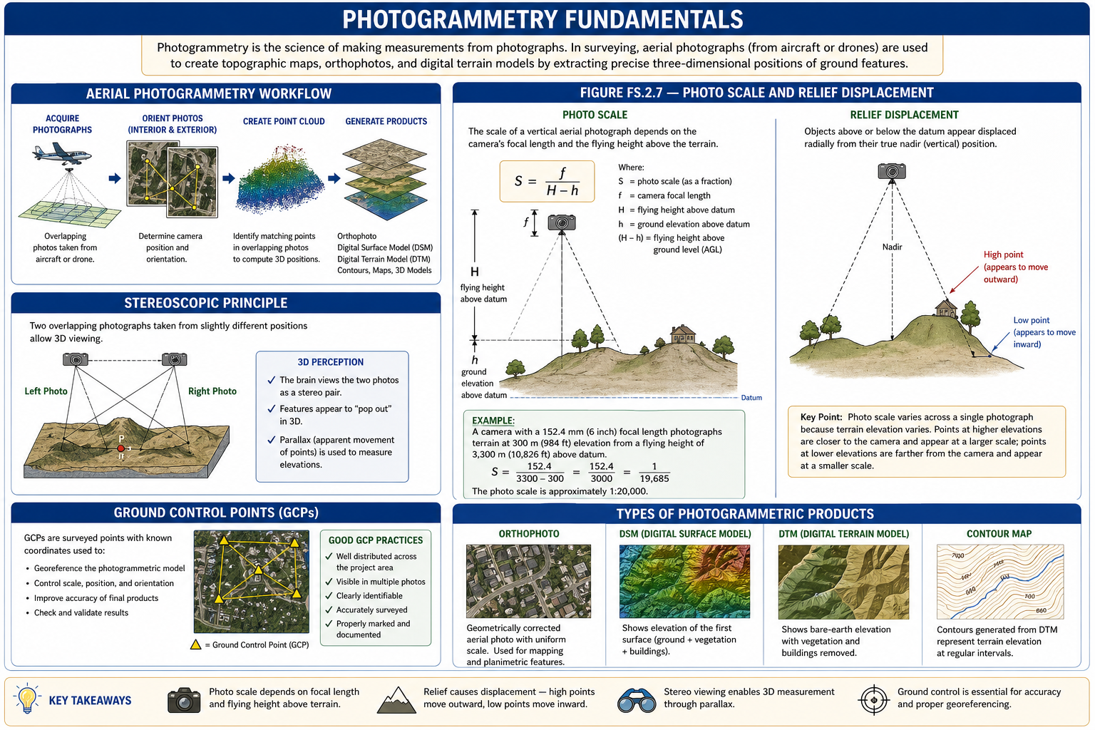
Photo Scale
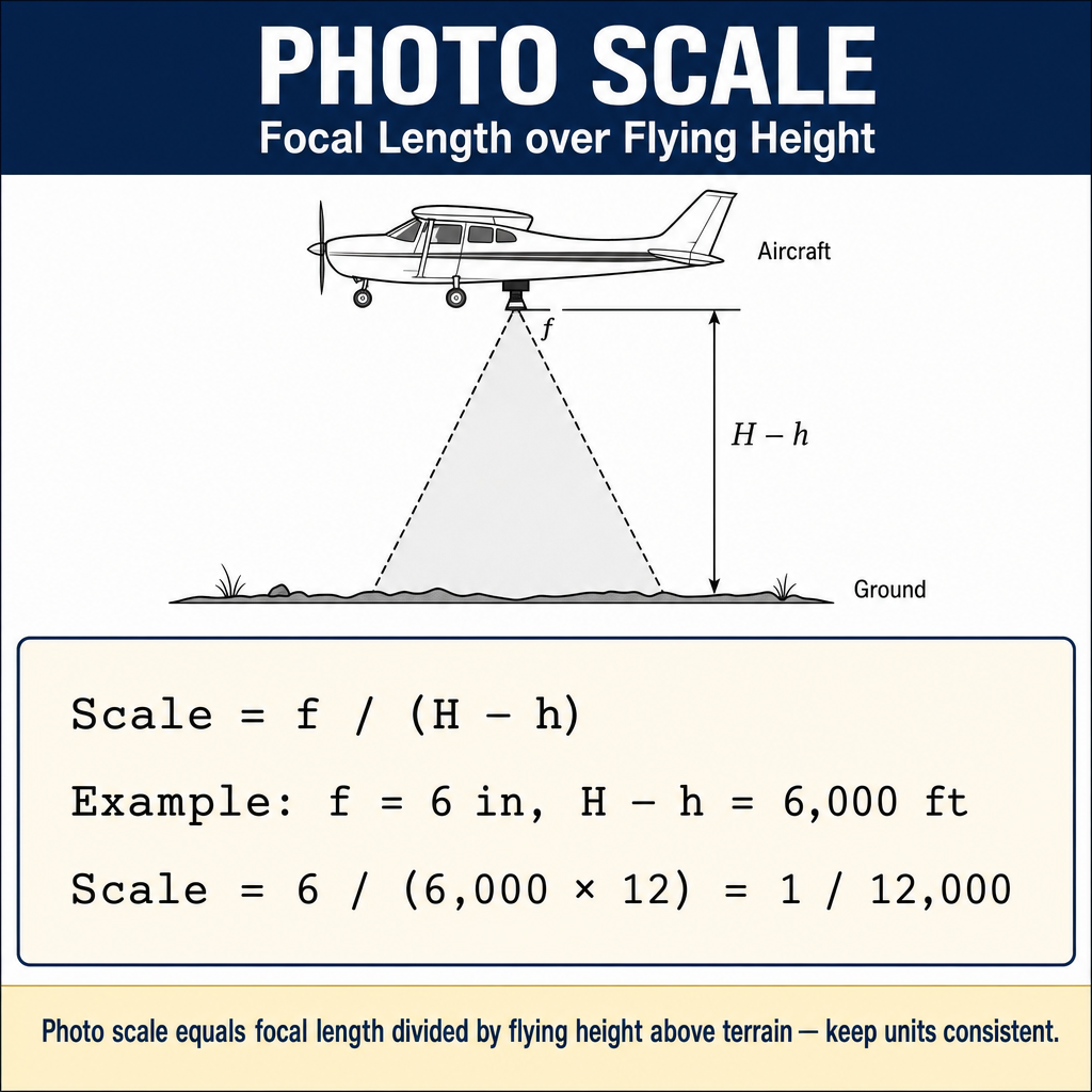
The scale of a vertical aerial photograph depends on the camera's focal length and the flying height above the terrain:
Where:
- S = photo scale (as a fraction, e.g., 1/12,000)
- f = camera focal length
- H = flying height above the datum
- h = ground elevation above the datum
- (H - h) = flying height above ground level (AGL)
Example: A camera with a 152.4 mm (6 inch) focal length photographs terrain at 300 m (984 ft) elevation from a flying height of 3,300 m (10,826 ft) above datum.
The photo scale is approximately 1:20,000.
Key point: Photo scale varies across a single photograph because terrain elevation varies. Points at higher elevations are closer to the camera and appear at a larger scale; points at lower elevations are farther from the camera and appear at a smaller scale.
Common wrong path — using flying height above datum instead of above ground level. The scale formula is — the denominator is the height above the terrain, not the absolute altitude. Students frequently plug in the flying height above sea level (or above datum) and forget to subtract the ground elevation, producing a scale denominator that's too large and a photo scale that's too small. For terrain 1,000 ft above sea level photographed from 10,000 ft altitude, the correct AGL is 9,000 ft — not 10,000. A 10% error in scale is substantial when translating photo measurements to ground distances. Exam questions explicitly give both H and h to test this — if you don't subtract, you will get the wrong answer.
Quick retrieval check — try before reading on.
▶A camera with 6-inch (152.4 mm) focal length photographs a project site at 850 ft ground elevation from a flying altitude of 8,350 ft above mean sea level. What is the photo scale?
Flying height AGL = H − h = 8,350 − 850 = 7,500 ft.
Converting focal length: 152.4 mm = 0.5 ft (6 inches).
.
The photo scale is 1:15,000. If you had used 8,350 ft directly without subtracting ground elevation, you'd get 1:16,700 — an 11% scale error, corresponding to distance errors of the same magnitude on any measurements taken from the photograph. Also note the units have to be consistent: either both f and (H−h) in the same units (both feet, both meters), or both converted before dividing.
Relief Displacement
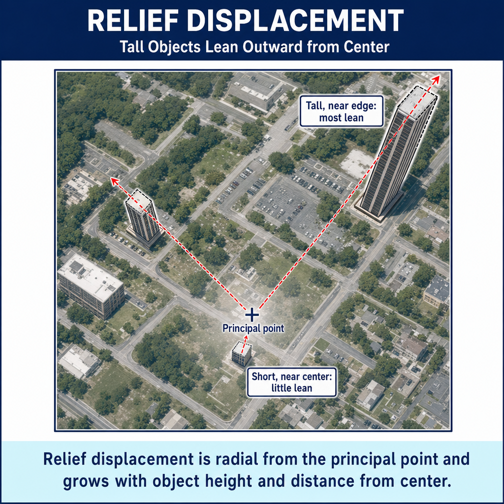
Relief displacement is the shift in the apparent position of a feature on an aerial photograph caused by its elevation above or below the datum plane. Objects above the datum are displaced radially outward from the photo center (nadir point); objects below the datum are displaced radially inward.
The relief displacement formula:
Where:
- d = relief displacement on the photo
- h = height of the object above the datum
- r = radial distance from the photo center (nadir) to the image of the top of the object
- H = flying height above the datum
Effects of relief displacement:
- Tall buildings appear to "lean away" from the center of the photograph
- The displacement is zero at the photo center and increases toward the edges
- This is why aerial photographs are not maps -- they contain geometric distortions due to relief
- Relief displacement must be removed to create orthophotos (geometrically corrected images)
Stereoscopic Viewing and Parallax
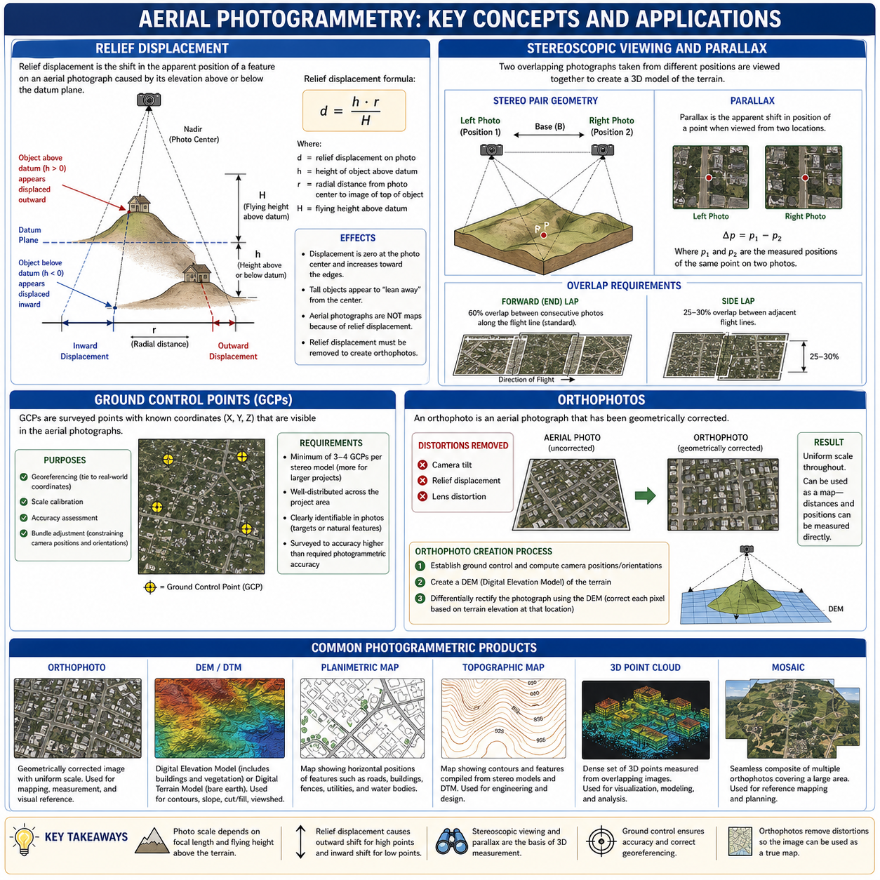
Stereoscopic viewing uses two overlapping photographs taken from different positions to create a three-dimensional model of the terrain. This is the basis for photogrammetric mapping.
Overlap requirements:
- Forward (end) lap: 60% overlap between consecutive photos along the flight line (standard); allows stereoscopic viewing
- Side lap: ~30% overlap between adjacent flight lines for film/airborne mapping (Ghilani & Wolf 13th ed., p. 794); UAS and digital workflows commonly use 50-70%; ensures complete coverage
Parallax is the apparent shift in position of a point when viewed from two different locations. In aerial photogrammetry, the parallax of a single point on a stereo pair is:
Where x_L and x_R are the photo x-coordinates of the same point measured (with algebraic sign) on the left and right prints, with the x-axis aligned along the flight line through each photo's principal point (Ghilani & Wolf, Elementary Surveying 13th ed., Eq. 27.10). Parallax is directly related to elevation: points at higher elevations have greater parallax than points at lower elevations. The parallax difference Δp between two points on the same stereo pair is then used to compute the elevation difference between those points.
Ground Control Points (GCPs)
Ground control points are surveyed points with known coordinates (X, Y, Z) that are visible in the aerial photographs. They are essential for:
- Georeferencing: Tying the photogrammetric model to real-world coordinates
- Scale calibration: Establishing accurate scale across the model
- Accuracy assessment: Verifying the accuracy of the photogrammetric products
- Bundle adjustment: Constraining the mathematical solution for camera positions and orientations
GCP requirements:
- Minimum of 3-4 GCPs per stereo model (more for larger projects)
- Well-distributed across the project area (not clustered)
- Clearly identifiable in the photographs (painted targets, natural features)
- Surveyed to accuracy higher than the required photogrammetric accuracy
Orthophotos
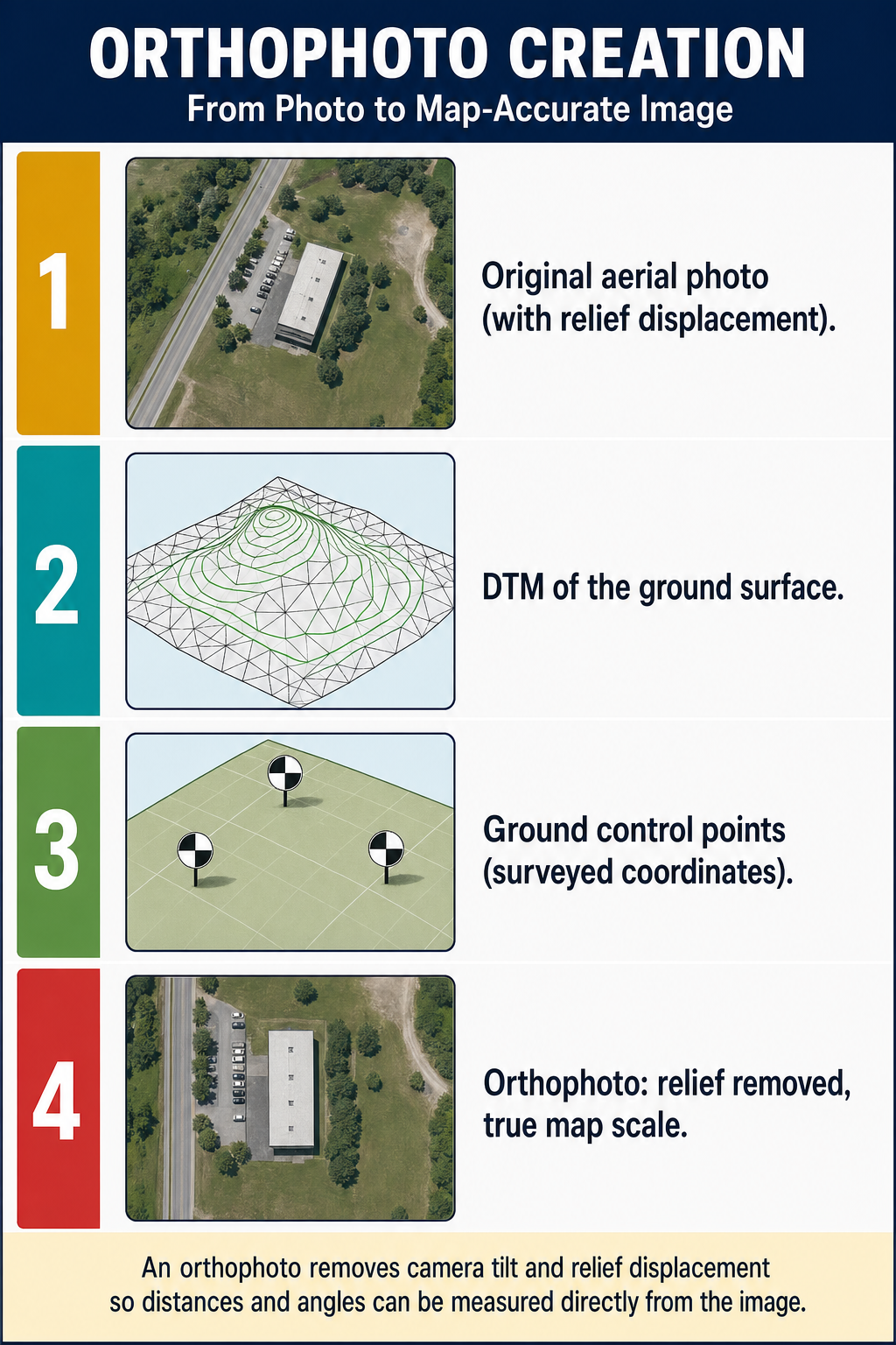
An orthophoto (or orthoimagery) is an aerial photograph that has been geometrically corrected to remove:
- Tilt of the camera at the time of exposure
- Relief displacement due to terrain variation
- Lens distortion
Result: An orthophoto has uniform scale throughout and can be used as a map -- distances and positions can be measured directly from it.
Orthophotos are created by:
- Establishing ground control and computing camera positions/orientations
- Creating a DEM of the terrain
- Differentially rectifying the photograph using the DEM (correcting each pixel individually based on the terrain elevation at that location)
Photogrammetric Products
| Product | Description |
|---|---|
| Orthophoto | Geometrically corrected image with uniform scale |
| DEM/DTM | Digital elevation/terrain model from stereo measurement |
| Planimetric map | Map showing horizontal positions of features (roads, buildings, etc.) |
| Topographic map | Map with contours and features compiled from stereo models |
| 3D point cloud | Dense set of 3D points measured from overlapping images |
| Mosaic | Seamless composite of multiple orthophotos covering a large area |
Exam Tips
- Photo scale = f / (H - h); photo scale varies with terrain elevation on a single photo
- Relief displacement is radial from the photo center; taller objects lean more, and displacement increases toward the photo edges
- 60% forward overlap and ~30% side lap are standard for film/airborne stereo coverage (UAS workflows commonly use 50-70% sidelap)
- Ground control points must be well-distributed and clearly visible in the photographs
- An orthophoto has been corrected for tilt and relief; it has uniform scale and can be used as a map
- An uncorrected aerial photograph is not a map because of relief displacement and tilt distortion
- The FS exam commonly tests photo scale calculations and the relief displacement formula
- Parallax is related to elevation: higher points have greater parallax
- Know the difference between a perspective photograph (has distortion) and an orthophoto (corrected)
Related Test Topics
- Remote Sensing, LiDAR, and UAS (Topic 2.8)
- Map Concepts and Cartography (Topic 2.1)
- Digital Terrain Models (Topic 2.6)
- Topographic Surveys (Module 1, Topic 1.7)
Further Reading
Authoritative sources for deeper study
Wolf, DeWitt & Wilkinson, Elements of Photogrammetry with Applications in GIS (4th Ed.) — Standard photogrammetry text covering geometry, stereo models, and aerotriangulation.
Penn State GEOG 482 — The Nature of Geographic Information — Open courseware on map projections, datums, and geospatial data fundamentals.
FGDC Geospatial Positioning Accuracy Standards — National standard for positional accuracy reporting (NSSDA).
Last updated: 2026-04-17