FS Exam Preparation
Comprehensive preparation for the Fundamentals of Surveying (FS) exam. 7 modules covering all 7 exam domains with 60 in-depth topics.
Module 1: Surveying Processes & Methods
Module 2: Mapping Processes & Methods
Module 3: Boundary Law & Real Property
Module 4: Surveying Principles & Geodesy
Module 5: Survey Computations
Module 6: Business Concepts
Levels & Level Instruments
Learning Objectives
After completing this topic, you should be able to:
- Describe the types of leveling instruments and their applications
- Perform differential leveling computations
- Calculate allowable misclosure for various orders of leveling
- Identify and correct for curvature and refraction
- Explain trigonometric leveling and its limitations
- Apply proper field procedures for precise leveling
Overview
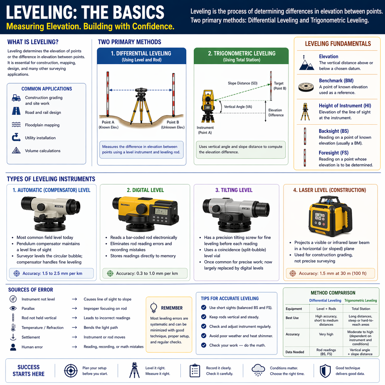
Leveling is the process of determining differences in elevation between points. It is one of the most fundamental surveying operations, required for virtually every type of project -- from construction grading to floodplain mapping. The FS exam tests your understanding of leveling instruments, field procedures, error sources, and computations.
The two primary methods are differential leveling (using a level instrument and rod) and trigonometric leveling (using a total station to compute elevation from vertical angle and slope distance).
Key Concepts
Types of Leveling Instruments
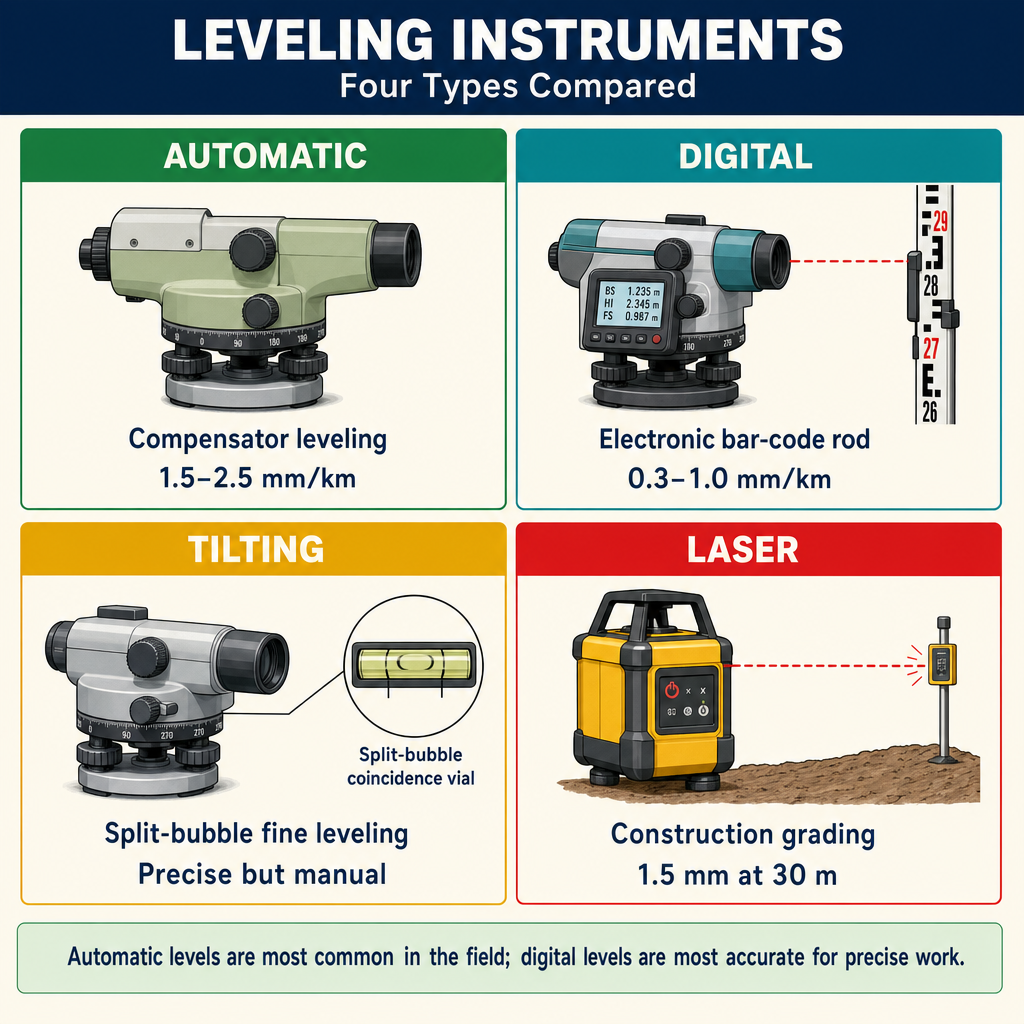
Automatic (compensator) level:
- Most common field level today
- Uses a pendulum compensator to maintain a level line of sight
- The surveyor levels the circular bubble; the compensator handles fine leveling
- Accuracy: typically 1.5 to 2.5 mm per km for standard models
Digital level:
- Reads a bar-coded rod electronically
- Eliminates rod reading errors and recording mistakes
- Stores readings directly to memory
- Accuracy: 0.3 to 1.0 mm per km for precise models
Tilting level:
- Has a precision tilting screw for fine leveling before each reading
- Uses a coincidence (split-bubble) level vial
- Once common for precise work; now largely replaced by digital levels
Laser level (construction):
- Projects a visible or infrared laser beam in a horizontal (or sloped) plane
- Used for construction grading, not precise surveying
- Accuracy: typically 1.5 mm at 30 m (100 ft)
Differential Leveling
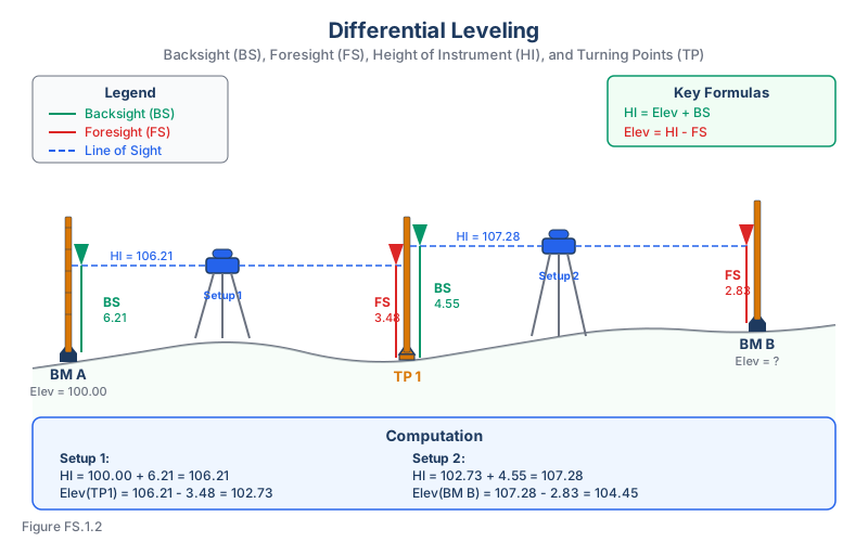
Differential leveling determines the elevation difference between two points by taking a series of backsight (BS) and foresight (FS) readings on a leveling rod.
Core concept. You are not measuring elevation directly -- you are transferring elevation from a known point to an unknown point through the horizontal plane of the level's line of sight. Each setup follows the same three-step pattern:
- Measure up from a known point (backsight)
- Establish the line-of-sight elevation (HI = known elevation + BS)
- Measure down to the new point (new elevation = HI - FS)
The fundamental relationship:
Or equivalently, using the Height of Instrument (HI) method -- the most common field workflow because it simplifies bookkeeping when one setup produces multiple foresights:
Where HI is the Height of Instrument (the elevation of the line of sight).
Key terminology:
- Benchmark (BM): A point of known elevation -- the starting (and ideally closing) reference for any leveling run. May be published (NGS monument, local control) or assumed (arbitrary but stable).
- Backsight (BS): A rod reading on a point of known elevation; used to compute HI.
- Foresight (FS): A rod reading on a point of unknown elevation; used to compute that point's elevation from the current HI.
- Turning point (TP): A stable intermediate point used when the next point is beyond the instrument's useful range. The TP receives a FS from the previous setup and a BS for the next setup -- it chains elevation through multiple instrument positions.
Field Workflow
Single setup ("one leg"):
- Set up the level roughly between the benchmark and the new point
- Read BS on the benchmark → compute HI
- Read FS on the new point → compute its elevation
Multi-setup level run: When the benchmark and target are too far apart for a single setup, chain through turning points. Each TP receives a FS (closing the previous leg) and a BS (opening the next leg). Elevation propagates from BM through each TP to the final point.
Level loop (quality control): Start on a benchmark, run the level through every target point, and return to the same benchmark (or close on a second known BM). If the closing elevation does not match the known elevation, the difference is the misclosure -- a direct measure of accumulated error over the whole loop. Loops are the gold-standard check for detecting blunders and evaluating run quality.
Field Best Practices
Balance backsight and foresight distances. Keeping BS and FS sight lengths approximately equal at every setup cancels three of the biggest systematic errors at once: collimation (line of sight not truly level), earth curvature, and atmospheric refraction. This single habit does more for accuracy than any equipment upgrade.
"Break the legs" between setups. After each BS/FS pair, physically pick up the tripod, move it, re-level, and resume. Re-leveling between setups detects instrument drift, disturbs systematic bias from a single bad setup, and forces fresh focus on each reading. Precise-order work requires it.
Avoid side shots for precise work. Taking multiple foresights from one setup (to side-shoot topographic points, for example) is fine for mapping but reduces redundancy for vertical control. Each side shot shares the same HI error; there is no independent check. For control leveling, move the instrument and re-measure.
Do the math in the field. Compute HI, each new elevation, and a running sum of BS - FS before leaving the site. If the arithmetic disagrees with an expected elevation, or if the BS/FS sums do not reconcile, you can re-read or re-set on the spot -- catching an error at the site is free; returning to it the next day is not.
Standard Field Note Format
Traditional differential-leveling field notes use a five-column layout that mirrors the computation flow:
| Point | BS (+) | HI | FS (-) | Elev |
|---|---|---|---|---|
| BM | 6.1 | 100.0 | ||
| 106.1 | ||||
| TP 1 | 9.7 | 5.5 | 100.6 | |
| 110.3 | ||||
| TP 2 | 4.8 | 105.5 |
The plus (+) sign on the BS column is a reminder that backsights are added to the elevation of the point they are read on (to compute HI). The minus (−) sign on the FS column reminds you that foresights are subtracted from HI to compute the new elevation. The HI row is intentionally offset below the BS row -- it visually reinforces that HI is computed from the BS just above it, and that all FS readings taken from the same setup use the HI on that line. A second common arrangement places the BS next to its HI on the same line; both conventions are acceptable as long as they are used consistently. Finished-grade and cut/fill columns can be appended on the right when leveling is tied to construction stakes.
Field-check rule: the sum of all BS readings minus the sum of all FS readings on turning points should equal the difference between the starting and ending benchmark elevations. If it doesn't, there is an arithmetic error somewhere in the notes. Source: Basic Surveying Manual (Wisconsin LTAP, 2002), "Survey notes."
One-Person Leveling with a Hand Level
Single-person crews (grade-stake resets, solo equipment operators, utility verifications) cannot use a standard level-and-rod technique -- one person can't simultaneously hold a rod on a distant point and read the instrument. The standard workaround uses a hand level braced on a lath:
- At a point of known elevation, mark a horizontal line on a lath at a convenient height above the point (for example, 3.0 ft above the BM). The elevation of that line is BM + 3.0.
- Move to the unknown point and rest the hand level alongside a level rod. Sight back at the marked lath and read where the hand level's line of sight crosses the rod. That reading is the height of the hand-level line on the rod.
- The elevation difference between the two points is computed as:
(height on lath) - (reading on rod) = ΔElev. The unknown point's elevation equals the BM elevation plus this difference.
Because the hand level replaces the instrument at each setup, accuracy is lower (typically tenths of a foot over reasonable distances) and sight lines should be kept short. This technique is adequate for resetting grade stakes, rough construction checks, and anywhere tenths-of-a-foot accuracy is sufficient. Source: Basic Surveying Manual (Wisconsin LTAP, 2002), "One person leveling."
Level Circuit and Misclosure
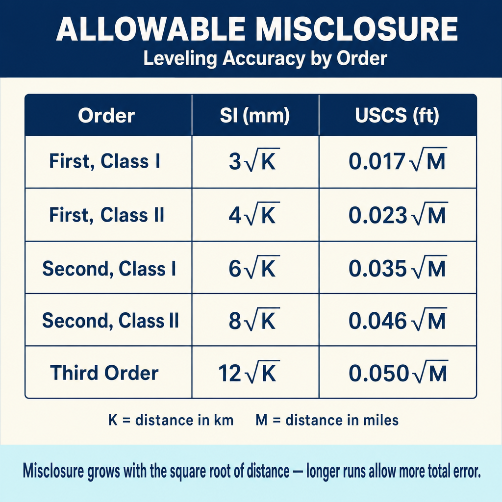
A level circuit starts at a known benchmark and closes on the same (or another known) benchmark. The difference between the computed closing elevation and the known elevation is the misclosure.
Allowable misclosure depends on the order of accuracy. The FGCS standard for loop misclosure (a circuit that begins and ends on the same benchmark) is :
| Order | Loop misclosure (SI) | Loop misclosure (USCS) |
|---|---|---|
| First Order, Class I | 4 mm × √K | 0.017 ft × √M |
| First Order, Class II | 5 mm × √K | 0.021 ft × √M |
| Second Order, Class I | 6 mm × √K | 0.025 ft × √M |
| Second Order, Class II | 8 mm × √K | 0.033 ft × √M |
| Third Order | 12 mm × √K | 0.050 ft × √M |
Where K = distance in kilometers, M = distance in miles. For a section (a line of levels that begins on one benchmark and closes on a different benchmark, no return), the constant for First Order Class I drops to 3 mm — the other classes use the same constants for sections and loops. Source: Ghilani & Wolf, Elementary Surveying (13th ed.), §5.5, citing the FGCS Standards and Specifications for Geodetic Control Networks (1984).
Curvature and Refraction
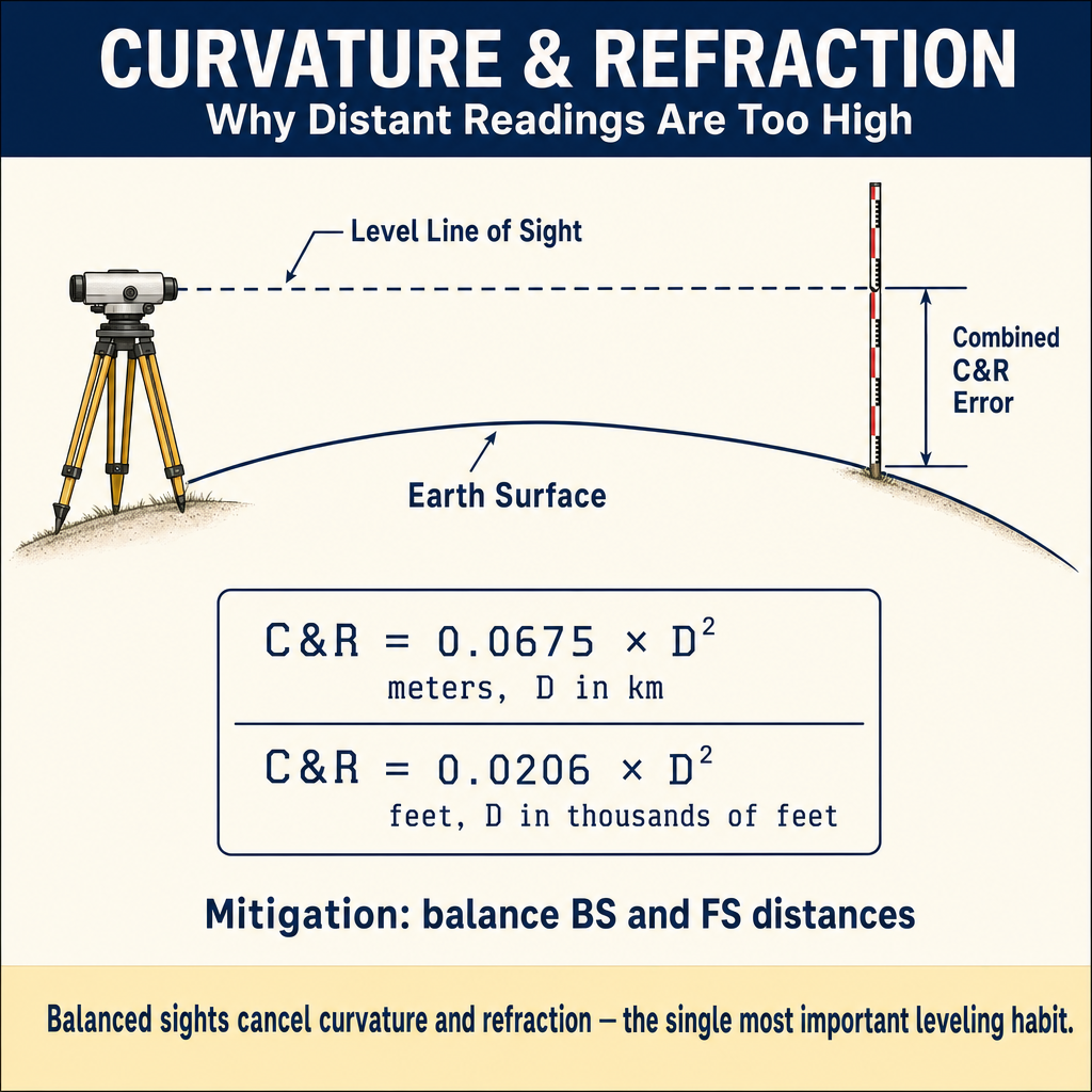
The level line of sight is a straight line, but the earth curves away beneath it, and atmospheric refraction bends the line of sight downward. These effects combine:
The combined effect makes distant rod readings too high. For a sight distance of 100 m (328 ft), the combined effect is less than 1 mm. For 300 m (984 ft), it is about 6 mm (0.02 ft).
Mitigation: Keeping backsight and foresight distances equal cancels the curvature and refraction effect (balanced sights).
Trigonometric Leveling
When differential leveling is impractical (steep terrain, long distances), trigonometric leveling uses a total station to determine elevation differences:
Where S is the slope distance, alpha is the vertical angle from horizontal, hi is the instrument height, and ht is the target height. If the instrument reports zenith angles instead, use , where z is the zenith angle measured from vertical.
Accuracy considerations:
- Less accurate than differential leveling for most applications
- Vertical angle errors propagate directly into elevation
- Atmospheric refraction affects the vertical angle
- Reciprocal observations (from both ends) reduce refraction effects
Sources of Error in Leveling
| Error | Type | Mitigation |
|---|---|---|
| Collimation (line of sight not level) | Systematic | Balance BS/FS distances; peg test |
| Rod not plumb | Systematic | Use rod level; wave rod for low readings |
| Earth curvature and refraction | Systematic | Balance BS/FS distances |
| Settlement of turning points | Systematic | Use firm surfaces; pin-type TPs |
| Rod reading errors | Random | Use digital level; careful reading |
| Parallax | Random | Focus eyepiece and objective properly |
| Temperature effects on rod | Systematic | Use invar rods for precise work |
| Instrument settlement | Random | Do not touch tripod; check readings |
A tilted rod always reads high — the direction of tilt doesn't matter. The rod's graduations are printed along the rod itself, so when the rod is tilted by angle from vertical, a horizontal line of sight at true elevation above the rod's foot intercepts the rod at slant length — not at . Because for any tilt, the slant length read off the tilted rod is always larger than the true plumb reading, no matter which way the rod leans. The correction is
So a 3° tilt at a 5-ft reading produces about 0.007 ft (2 mm) of error; at a 12-ft reading, about 0.016 ft. The error grows with both the reading and the square of the tilt. The practical rule: use a rod level and plumb the rod at every reading — don't try to diagnose tilt after the fact.
Quick retrieval check — try before reading on.
▶A rod 8.0 ft long is tilted 3° out of plumb. At a crosshair reading of 5.00 ft on the tilted rod, what is the approximate error, and in which direction?
The true (plumb) rod reading would be ft. The error is +0.007 ft — the tilted-rod reading is high by about 0.007 ft (2 mm). For a 5-ft reading with a 3° tilt the error is small, but it scales with the reading: at a 9-ft reading the error would be 0.012 ft, and at 12 ft (if the rod is that tall) it would be 0.016 ft. For precise leveling, 3° of tilt at a 5-ft reading already approaches the 1-mm-per-km loop closure tolerance for First Order Class I. Use a rod level and keep the rod plumb at every setup — it costs seconds and saves millimeters.
Common Field Mistakes
Beyond the theoretical error sources above, a handful of practical mistakes cause most real-world leveling errors:
- Reading the wrong footmark. Extendable rods show the current foot in a small red secondary number; beginners sometimes read the full-size foot digit at the bottom of the sight (one foot too low or too high). The fix: always read up from the footmark below. If the footmark isn't visible in the sight, have the rod person raise the rod slowly until it appears.
- Skipping a rod section. Telescoping rods must be fully extended before reading. A section left partially collapsed produces a reading that is consistently one section short.
- Rod held on the wrong point. At turning points especially, the rod person and instrument person must agree on exactly which point is the TP. A difference of even a few inches on a rocky TP can exceed the accuracy budget for the whole run.
- Rod not vertical. The rod person should stand directly behind the rod and hold it with both hands, lightly gripping so the rod's own plumb can take effect. A rod level is faster than trying to eye plumb.
- Heat-shimmer refraction near warm ground. Measurements taken within a foot of hot pavement or sun-warmed soil are degraded by air shimmer. Set up so the line of sight stays at least one foot above the ground, and favor mornings in summer.
- Benchmark choices that can't be re-found. For project-local BMs, use features that a later surveyor can relocate: top nut of a fire hydrant, chiseled mark on a curb, a spike driven in a tree or pole, a sewer-inlet top. An unmarked point painted on dirt is effectively a one-visit benchmark.
Source: Basic Surveying Manual (Wisconsin LTAP, 2002), "Common leveling mistakes."
The Peg Test (Two-Peg Test)
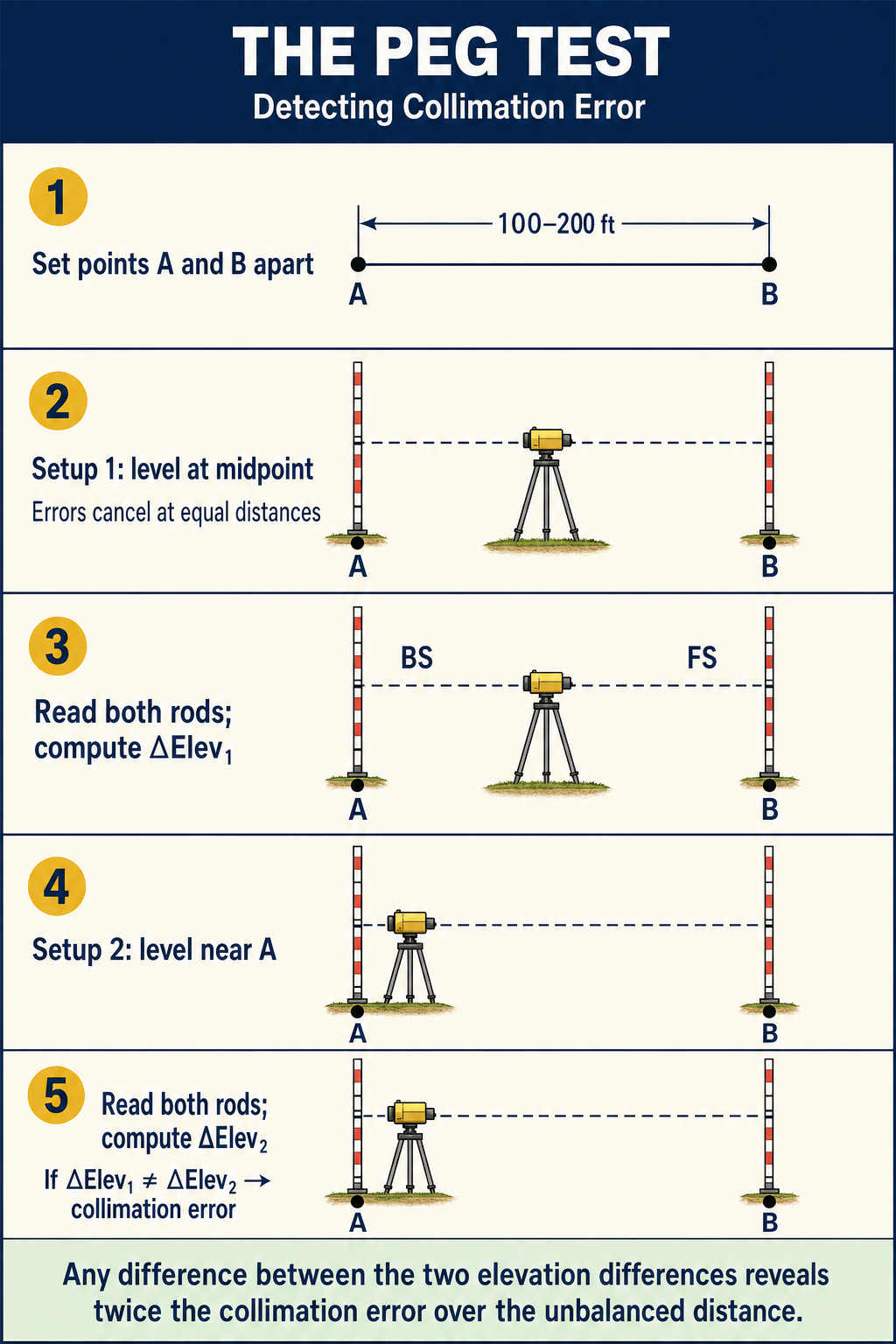
The peg test determines if the line of sight is truly level (i.e., if there is a collimation error). The procedure:
- Set two points A and B about 30-60 m (100-200 ft) apart
- Set up the level midway between A and B; read both rods (errors cancel at equal distances)
- Move the level close to one point (say A); read both rods again
- Compare the two elevation differences -- any discrepancy is twice the collimation error over the unbalanced distance
- Adjust the instrument or compute a correction factor
Key Takeaway
Differential leveling works because the level creates a horizontal plane of sight, and every rod reading is a vertical offset from that plane. Elevation transfers from a known BM to any new point as a chain of BS/FS pairs. Accuracy is governed more by procedure and discipline -- balanced sights, breaking the legs, plumbing the rod, closing the loop -- than by the instrument itself.
Exam Tips
- Balanced sights eliminate curvature, refraction, and collimation errors -- this is the single most important leveling procedure
- Know the differential leveling computation: HI = Elev + BS; Elev = HI - FS
- Misclosure formulas use the square root of the distance -- be ready to compute this
- The peg test checks for collimation error; know the procedure
- Trigonometric leveling is less accurate than differential leveling in most situations
- A turning point must be stable and receive both a FS and a BS
- Rod readings increase as you go down (a higher rod reading means a lower elevation for the same HI)
- The FS exam commonly asks for level circuit computations and allowable misclosure
- Watch for sign errors on BS (+) vs. FS (-) in circuit computations -- swapping them is the single most common mistake on exam problems
- Do not confuse HI (elevation of the line of sight) with the elevation of a point -- they differ by the rod reading
- Closing on the starting benchmark is the only way to quantify accumulated error; a run that does not close has no independent check
Related Test Topics
- Control Surveys and Standards (Topic 1.5)
- Vertical Surveys and Leveling (Module 4, Topic 4.2)
- Field Documentation (Topic 1.10)
Further Reading
Authoritative sources for deeper study
Wolf & Ghilani, Elementary Surveying — An Introduction to Geomatics (13th Ed., 2012) — Comprehensive surveying text covering instruments, field procedures, and computations.
Kavanagh, Surveying with Construction Applications (7th Ed.) — Combined surveying and construction-layout reference.
Allan, Principles of Geospatial Surveying (Ethernet Edu mirror) — Survey of geospatial principles, instruments, and adjustment.
Last updated: 2026-04-23