FS Exam Preparation
Comprehensive preparation for the Fundamentals of Surveying (FS) exam. 7 modules covering all 7 exam domains with 60 in-depth topics.
Module 1: Surveying Processes & Methods
Module 2: Mapping Processes & Methods
Module 3: Boundary Law & Real Property
Module 4: Surveying Principles & Geodesy
Module 5: Survey Computations
Module 6: Business Concepts
Total Stations & Electronic Distance Measurement
Learning Objectives
After completing this topic, you should be able to:
- Explain how Electronic Distance Measurement (EDM) works
- Describe the components and capabilities of a modern total station
- Calculate atmospheric corrections for EDM measurements
- Apply prism constant corrections
- Identify sources of error in total station measurements
- Distinguish between reflectorless and prism-based measurement modes
Overview
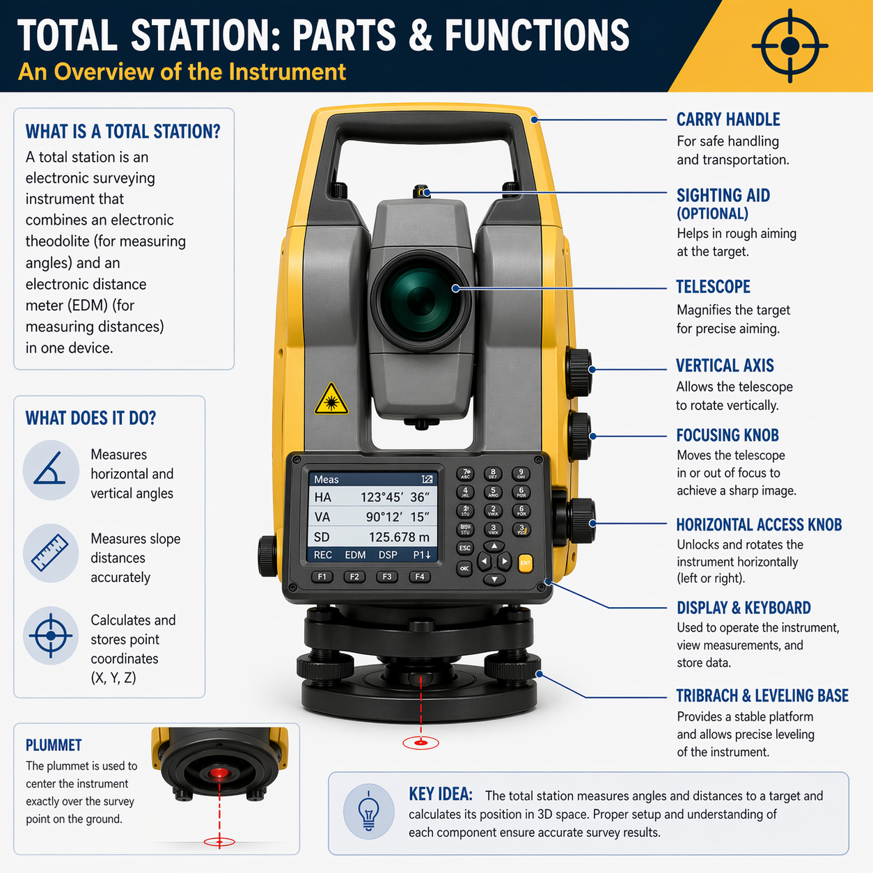
A total station is the primary instrument for measuring horizontal angles, vertical angles, and slope distances in modern surveying. It combines an electronic theodolite with an integrated EDM, allowing the surveyor to measure both angles and distances from a single setup. Modern total stations also include onboard processors for coordinate computation, data storage, and robotic tracking.
The Electronic Distance Measurement (EDM) component uses electromagnetic radiation -- typically infrared or laser light -- to measure the distance between the instrument and a target. Understanding how EDM works is fundamental to interpreting measurement accuracy and identifying error sources.
Key Concepts
How EDM Works
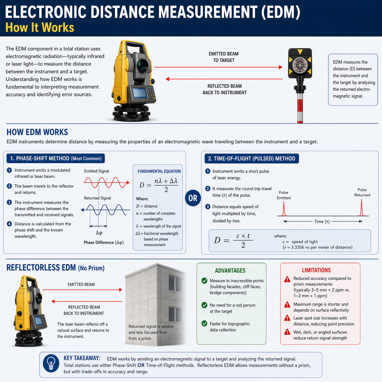
EDM instruments determine distance by measuring the properties of an electromagnetic wave traveling between the instrument and a reflector (or surface in reflectorless mode).
Phase-shift method (most common):
- The instrument emits a modulated infrared or laser beam
- The beam travels to the reflector and returns
- The instrument measures the phase difference between the transmitted and received signals
- Distance is calculated from the phase shift and the known wavelength
The fundamental equation:
Where D is the distance, n is the number of complete wavelengths, and the delta-lambda term represents the fractional wavelength from the phase measurement.
Pulsed (time-of-flight) method:
- The instrument emits a short pulse of laser energy
- It measures the round-trip travel time of the pulse
- Distance equals speed of light multiplied by time, divided by two
Atmospheric Corrections
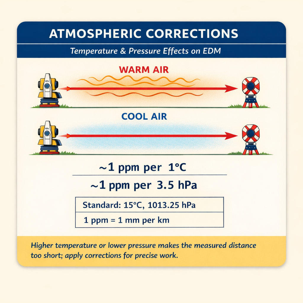
The speed of electromagnetic radiation varies with atmospheric conditions. EDM instruments are calibrated for standard conditions (typically 15 degrees C and 1013.25 hPa / 760 mm Hg). When field conditions differ, a correction must be applied.
Factors affecting the correction:
- Temperature -- higher temperature decreases air density, increasing the speed of light, making the measured distance too short
- Atmospheric pressure -- lower pressure decreases air density with the same effect
- Humidity -- has a small but measurable effect; often ignored for distances under 5 km
Typical correction magnitude: approximately 1 ppm (1 mm per km) per 1 degree C change or per 3.5 hPa pressure change (Ghilani & Wolf, Elementary Surveying, 13th Ed., §6.18; consistent with manufacturer specifications for Leica, Trimble, and Topcon total stations).
Application: Most modern instruments accept temperature and pressure inputs and compute the correction automatically. For precise work, measure conditions at both ends of the line and average.
Prism Constants
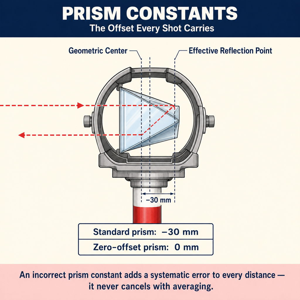
A prism constant (also called the prism offset) accounts for the difference between the geometric center of the prism and the effective reflection point of the EDM signal.
- Standard survey prisms typically have a constant of -30 mm or 0 mm depending on manufacturer
- The prism constant must be entered into the total station or applied post-processing
- An incorrect prism constant produces a systematic error in every distance measurement
- Mixing prism brands without adjusting the constant is a common source of error
Reflectorless EDM
Modern total stations can measure distances without a prism by using a laser beam that reflects off natural surfaces.
Advantages:
- Measure to inaccessible points (building facades, cliff faces, bridge components)
- No need for a rod person at the target
- Faster for topographic data collection
Limitations:
- Reduced accuracy compared to prism measurements (typically 3-5 mm + 2 ppm vs. 1-2 mm + 1 ppm; representative of current Leica TS16, Trimble S9, and Topcon GT-series total-station spec sheets)
- Maximum range is shorter and depends on surface reflectivity
- The laser spot size increases with distance, reducing point precision
- Wet, dark, or angled surfaces reduce return signal strength
Sources of Error
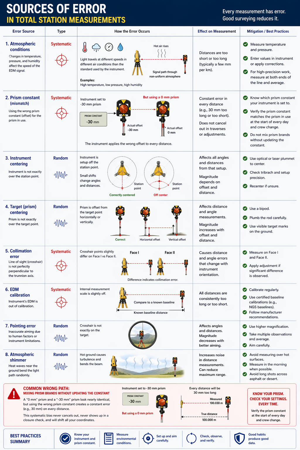
| Error Source | Type | Mitigation |
|---|---|---|
| Atmospheric conditions | Systematic | Measure temp/pressure; apply corrections |
| Prism constant | Systematic | Verify and enter correct constant |
| Instrument centering | Random | Use optical/laser plummet; tribrach check |
| Target centering | Random | Use bipod, care in plumbing rod |
| Collimation error | Systematic | Measure Face I and Face II; adjust |
| EDM calibration | Systematic | Regular baseline calibrations (NGS baselines) |
| Pointing error | Random | Multiple observations; increase magnification |
| Atmospheric shimmer | Random | Avoid measuring in heat shimmer; measure in AM |
Common wrong path — mixing prism brands without updating the constant. Prism constants vary by manufacturer. A "zero-offset" survey prism (0 mm) and a "-30 mm" prism look nearly identical in the field, but measuring with one while the instrument is configured for the other produces a constant 30 mm (about 0.1 ft) error on every shot. That error is a systematic bias — it never cancels with averaging, it never goes away with more measurements, and it never shows up in the closure check because it affects every distance equally. Students and field crews alike fall into this trap when they grab a "backup" prism from another crew's vehicle. The only defense: know which prism constant your instrument is set to, and verify it matches the prism in use, at the start of every day and at every crew change. Exam questions may describe a traverse that closed perfectly to within a few millimeters but "something seems wrong with the coordinates" — suspect a prism-constant mismatch if the error is systematic and approximately equal in magnitude to a prism offset.
Quick retrieval check — try before reading on.
▶Your total station is set for a prism constant of −30 mm. Your rod person uses a zero-offset prism on 14 shots. How large is the systematic error in each shot, and how does it manifest in a closed traverse?
Each shot is in error by 30 mm (≈ 0.098 ft) — the difference between the −30 mm constant the instrument expected and the 0 mm constant of the prism actually used. Every distance is too short by 30 mm (because the instrument added a correction that shouldn't have been there). In a closed traverse, a systematic distance error of the same sign on every leg can still produce a small closure error (because the error components in lat and dep depend on bearings and may partially cancel), so the closure check alone won't catch it. The clue is that the coordinates of known control points won't match — for instance, comparing your computed coordinate of a second tied control station against its published value may show a ~40 mm horizontal difference (roughly 30 mm × number of legs / some geometric factor). Absolute checks against known control are the only reliable way to detect this kind of systematic bias.
Total Station Setup Procedure
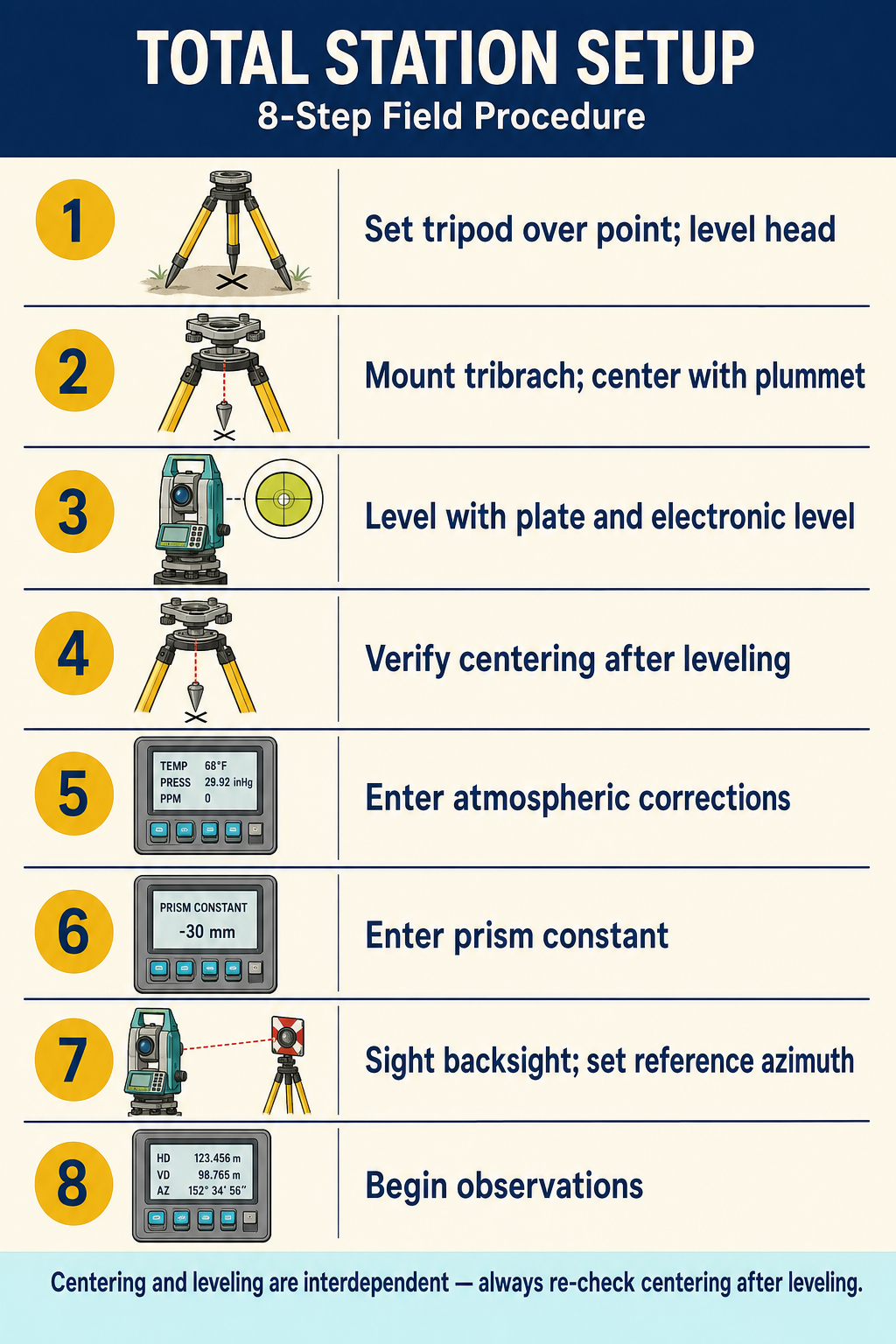
- Set up tripod over the point; level the head approximately
- Mount the tribrach; center over the point using optical or laser plummet
- Level the instrument using the plate level and electronic level
- Verify centering after leveling (centering and leveling are interdependent)
- Enter atmospheric corrections (temperature, pressure)
- Enter prism constant for the target being used
- Sight the backsight and set the reference azimuth
- Begin observations
Quick Field Techniques and Independent Checks
Even with a total station in hand, the fastest way to catch a blunder -- a bad point number, a wrong prism constant, a transposed offset -- is an independent check by a crude method. Two techniques are worth knowing:
Pacing -- count steps over a known distance to calibrate your natural pace length (typically 2.5-3.0 ft / 0.76-0.91 m per step; experienced pacers reach 1/50 to 1/100 precision on open level ground). Use pacing to validate: after an EDM measurement reads 347.2 ft, a quick pace should produce something in the 330-365 ft range. A pace result wildly out of range means a measurement blunder or a transposed setup. Always use your natural pace, not a forced even-foot step -- an unnatural pace drifts over long distances, especially uphill.
3-4-5 triangle for field right angles -- any multiple of 3, 4, 5 forms a right triangle (the hypotenuse being the longest side). Common field setup: from a baseline, measure 15 ft along the line and 20 ft across; the diagonal between those two points must equal 25 ft if the cross distance is a true right angle. If the diagonal reads 24 ft or 26 ft, the cross is off and needs adjustment. This is the fastest way to square a layout without an instrument. Source: Basic Surveying Manual (Wisconsin LTAP, 2002), "Pacing" and "Right triangles."
Horizontal vs. slope distance -- the table. Surveying always works in horizontal distance, not slope distance, because horizontal distance is invariant to ground disturbance. For rough slopes, the difference is small; for steep slopes, it matters:
| Slope (V:H) | Horizontal distance for 100 ft slope |
|---|---|
| 1V:10H (10%) | 99.50 ft |
| 1V:6H (17%) | 98.64 ft |
| 1V:4H (25%) | 97.00 ft |
| 1V:3H (33%) | 94.87 ft |
| 1V:2H (50%) | 89.44 ft |
| 1V:1H (100%) | 70.71 ft |
For gentle terrain (shallower than ~1:10) and non-precise work, slope distance is usually acceptable. For anything steeper, convert to horizontal. Source: Basic Surveying Manual (Wisconsin LTAP, 2002), Table I.
Exam Tips
- Know the difference between phase-shift and pulsed EDM methods
- Atmospheric corrections are proportional to distance -- they are negligible for short distances and critical for long ones
- An incorrect prism constant affects every measurement by the same amount -- it is a systematic error
- Face I / Face II observations eliminate collimation and trunnion axis errors
- Reflectorless mode is less accurate than prism mode; know the typical accuracy specifications
- EDM calibration should be performed on an NGS calibration baseline at least annually
- The FS exam may ask you to compute a corrected distance given atmospheric conditions
Related Test Topics
- Control Surveys and Standards (Topic 1.5)
- Construction Surveys and Staking (Topic 1.8)
- Field Documentation (Topic 1.10)
Further Reading
Authoritative sources for deeper study
Wolf & Ghilani, Elementary Surveying — An Introduction to Geomatics (13th Ed., 2012) — Comprehensive surveying text covering instruments, field procedures, and computations.
Kavanagh, Surveying with Construction Applications (7th Ed.) — Combined surveying and construction-layout reference.
Allan, Principles of Geospatial Surveying (Ethernet Edu mirror) — Survey of geospatial principles, instruments, and adjustment.
Last updated: 2026-04-17