FS Exam Preparation
Comprehensive preparation for the Fundamentals of Surveying (FS) exam. 7 modules covering all 7 exam domains with 60 in-depth topics.
Module 1: Surveying Processes & Methods
Module 2: Mapping Processes & Methods
Module 3: Boundary Law & Real Property
Module 4: Surveying Principles & Geodesy
Module 5: Survey Computations
Module 6: Business Concepts
State Plane Coordinate Systems
Learning Objectives
After completing this topic, you should be able to:
- Explain the purpose and structure of the State Plane Coordinate System
- Distinguish between Lambert Conformal Conic and Transverse Mercator projections in SPCS
- Define scale factor, elevation factor, and combined factor
- Convert between grid distance and ground distance
- Understand convergence angle and grid vs. geodetic bearings
- Identify which projection type is used for different zone shapes
Overview
The State Plane Coordinate System (SPCS) is a set of map projections covering the United States, designed to provide a coordinate system for surveying and mapping with minimal distortion. Each state is divided into one or more zones, and each zone uses a specific map projection to keep the scale factor close to unity (1.0).
SPCS is the most commonly used coordinate system for local surveying in the United States. The FS exam tests your understanding of scale factors, grid-to-ground conversions, and the basic structure of the system.
Key Concepts
Purpose of SPCS
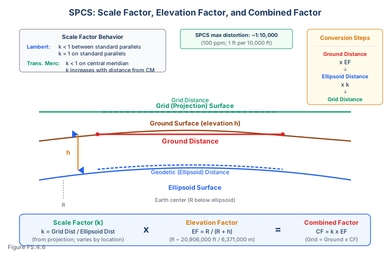
SPCS was developed to allow surveyors to work with plane coordinates (northing and easting on a flat grid) while keeping the distortion from projecting the curved earth onto a flat surface within acceptable limits.
Design constraints:
- Each zone is limited in width so that the maximum scale distortion does not exceed approximately 1:10,000 (100 ppm) (NOAA Manual NOS NGS 5, State Plane Coordinate System of 1983, Stem)
- This means a ground distance of 10,000 feet would be represented on the grid as between 9,999 and 10,001 feet
- For many survey applications, this distortion is negligible; for precise work, scale factors must be applied
Projection Types
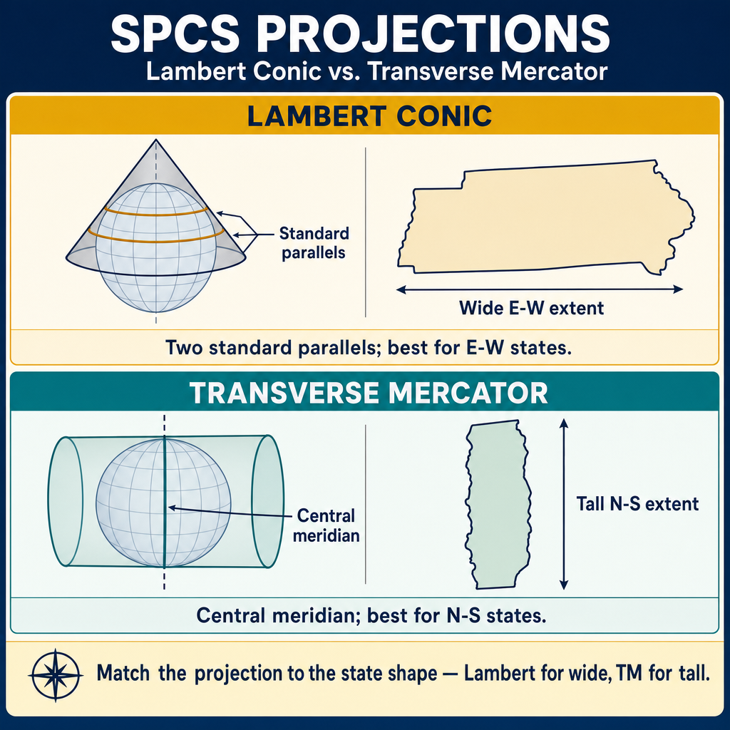
Lambert Conformal Conic projection:
- Used for zones that are wider east-west than north-south
- Two standard parallels where the cone intersects the ellipsoid (scale factor = 1.0 on these parallels)
- Between the standard parallels, the scale factor is less than 1.0 (grid distances are shorter than ground)
- Outside the standard parallels, the scale factor is greater than 1.0
- Used by most states for their SPCS zones
Transverse Mercator projection:
- Used for zones that are longer north-south than east-west
- Has a central meridian where the cylinder intersects the ellipsoid
- Scale factor is less than 1.0 on the central meridian and increases with distance from it
- Used for narrow, north-south oriented zones
Oblique Mercator:
- Used for one zone: the Alaska panhandle (Zone 1)
- The cylinder axis is oblique to the earth's axis
Scale Factor
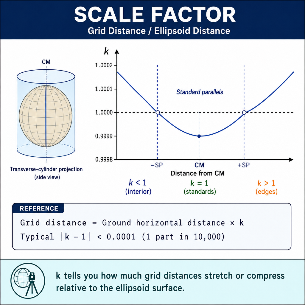
The scale factor (k) is the ratio of a distance on the grid to the corresponding distance on the ellipsoid:
For Lambert Conformal Conic:
- k < 1.0 between the standard parallels (grid distance is shorter)
- k = 1.0 on the standard parallels
- k > 1.0 outside the standard parallels
For Transverse Mercator:
- k < 1.0 on the central meridian (typically about 0.9999 to 0.99997)
- k increases with distance from the central meridian
Elevation Factor
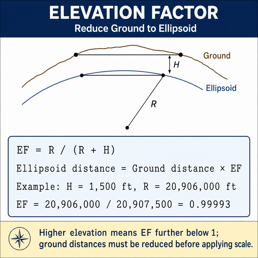
The elevation factor (also called the sea level factor) accounts for the difference between the ground surface and the ellipsoid:
Where R is the mean radius of the earth (approximately 20,902,000 ft, or 6,371,000 m) and h is the height above the ellipsoid.
At sea level (h = 0): Elevation factor = 1.0 At higher elevations: Elevation factor < 1.0 (ground distances are longer than ellipsoid distances)
Combined Factor
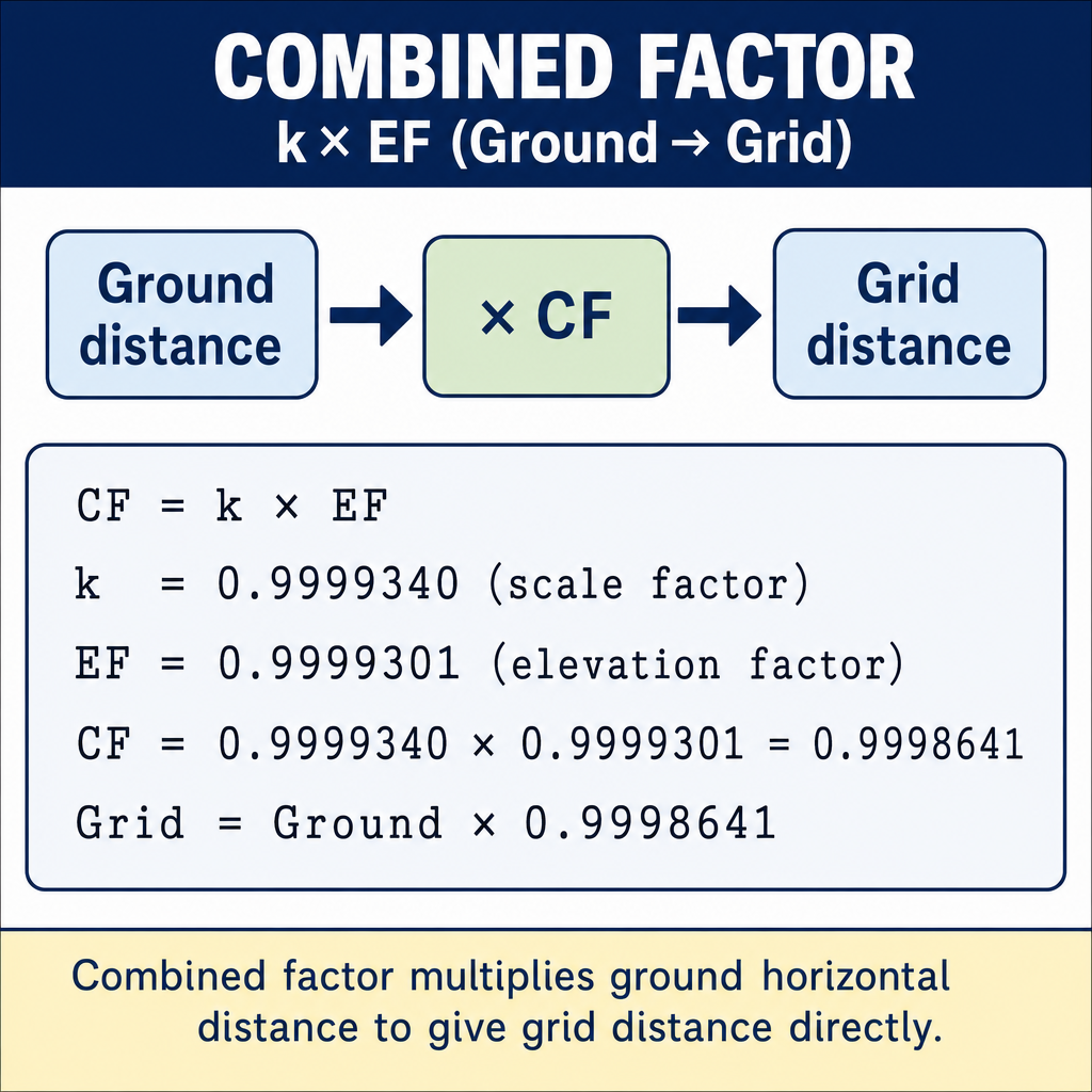
The combined factor is the product of the scale factor and the elevation factor:
To convert ground distance to grid distance:
To convert grid distance to ground distance:
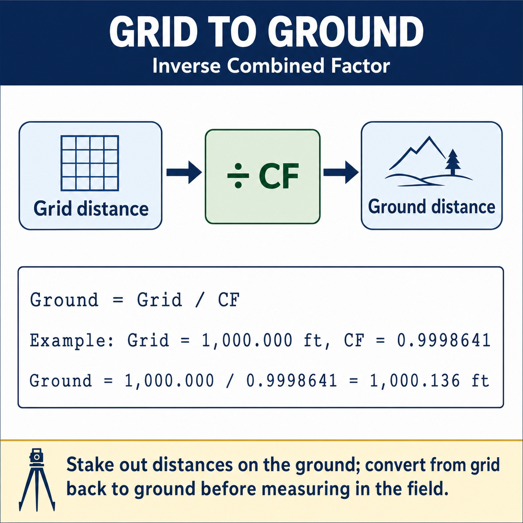
Example: A ground distance of 1,500.000 ft is measured at an elevation of 1,000 ft above the ellipsoid. The scale factor at the location is 0.99990.
Common wrong path — swapping the direction of the combined factor. The combined factor is less than 1.0 for most surveying work in the continental U.S. (typical CF: 0.9996 to 0.99999, with high-elevation Mountain West sites driving CF toward the lower end of that range). So:
- Ground → Grid: multiply by CF → grid is smaller than ground
- Grid → Ground: divide by CF → ground is larger than grid
Students often memorize "multiply by CF" without pairing it to the direction, then apply multiplication in both directions and end up with errors that are double the CF deviation from 1.0. Mnemonic: ground is big, grid is small — the projection squishes the curved earth onto a flat page. The flat grid is always the smaller of the two in a zone with CF < 1. On the exam, a distance question that says "convert the measured tape distance to the grid value on the plat" is ground → grid: multiply. "Stake this grid distance on the ground" is grid → ground: divide.
Quick retrieval check — try before reading on.
▶A plat shows a line of 850.00 ft (grid) on SPCS 83. The site has scale factor k = 0.99988 and elevation 2,400 ft above the ellipsoid (R = 20,902,000 ft). What is the ground distance you should stake?
Elevation factor = .
Combined factor = .
Ground distance = ft.
The ground stakeout distance is 0.20 ft longer than the grid value. Over a 5,000-ft lot line this accumulates to over 1 ft — easily enough to miss a property corner. Always check the combined factor before staking from grid coordinates.
Convergence Angle
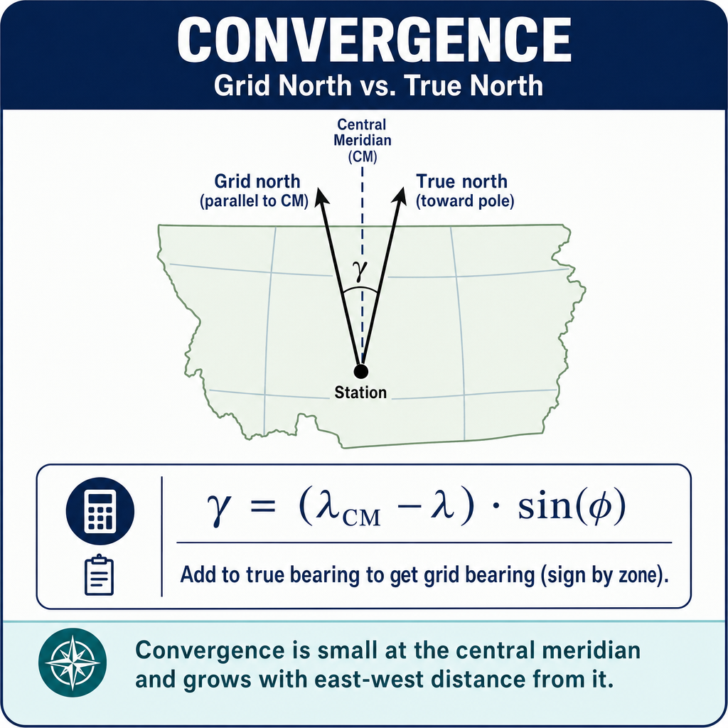
The convergence angle (gamma) is the angle between grid north (the direction of the northing axis) and geodetic (true) north at a point.
Where (t - T) is the arc-to-chord correction (second-order term, negligible for most surveys).
For practical purposes:
Convergence characteristics:
- Convergence is zero on the central meridian for both Transverse Mercator and Lambert Conformal Conic projections
- Convergence increases with distance from the central line
- The sign of convergence depends on the position relative to the central meridian/parallel
SPCS Zone Assignment
Each state has one or more SPCS zones:
| Zone Shape | Projection Type | Examples |
|---|---|---|
| East-west oriented | Lambert Conformal Conic | Texas, Colorado, Pennsylvania, Tennessee |
| North-south oriented | Transverse Mercator | Illinois, Indiana, New Jersey, Vermont |
| Single zone (small state) | Either | Connecticut (Lambert), Delaware (TM) |
Some states have many zones (e.g., Texas has 5, Alaska has 10); small states may have just one.
SPCS 83 vs. SPCS 27
- SPCS 27: Based on NAD 27 (Clarke 1866 ellipsoid); coordinates in US Survey feet
- SPCS 83: Based on NAD 83 (GRS 80 ellipsoid); coordinates in meters or feet (varies by state)
- SPCS 2022: Will be based on NATRF2022; currently under development
Do not mix SPCS 27 and SPCS 83 coordinates -- they differ by tens to hundreds of meters for the same point.
Exam Tips
- Lambert is for wide (east-west) zones; Transverse Mercator is for narrow (north-south) zones
- The combined factor = scale factor x elevation factor; use it to convert between ground and grid distances
- Grid distance = ground distance x combined factor; ground distance = grid distance / combined factor
- The scale factor is less than 1 between standard parallels (Lambert) or on the central meridian (TM)
- The elevation factor accounts for the height above the ellipsoid; it is always less than or equal to 1
- Convergence is the angle between grid north and geodetic north; it varies by location within the zone
- Know which projection type your state uses (this may be given in the problem)
- The FS exam commonly asks grid-to-ground distance conversion problems
- R = approximately 20,902,000 ft (≈ 6,371,000 m) for the elevation factor calculation
- Never mix SPCS 27 and SPCS 83 coordinates without proper transformation
Related Test Topics
- Map Projections and Grids (Topic 4.7)
- Datums and Conversions (Topic 4.5)
- Geodetic Coordinates and Surfaces (Topic 4.4)
- Horizontal Surveys and Methods (Topic 4.1)
Further Reading
Authoritative sources for deeper study
NOAA Manual NOS NGS 5 — State Plane Coordinate System of 1983 — Definitive NGS reference for SPCS83 zone constants, projections, and conversions.
Snyder, USGS Bulletin 1532 — Map Projections Used by the USGS — Mathematical treatment of common map projections (Lambert Conformal Conic, Transverse Mercator, etc.).
Wolf & Ghilani, Elementary Surveying — Chapter on map projections and the State Plane Coordinate System.
NGS Geodetic Glossary (1986, NOAA repository) — Authoritative definitions for geodetic, GNSS, and surveying terms.
Last updated: 2026-04-17